Constraint Region
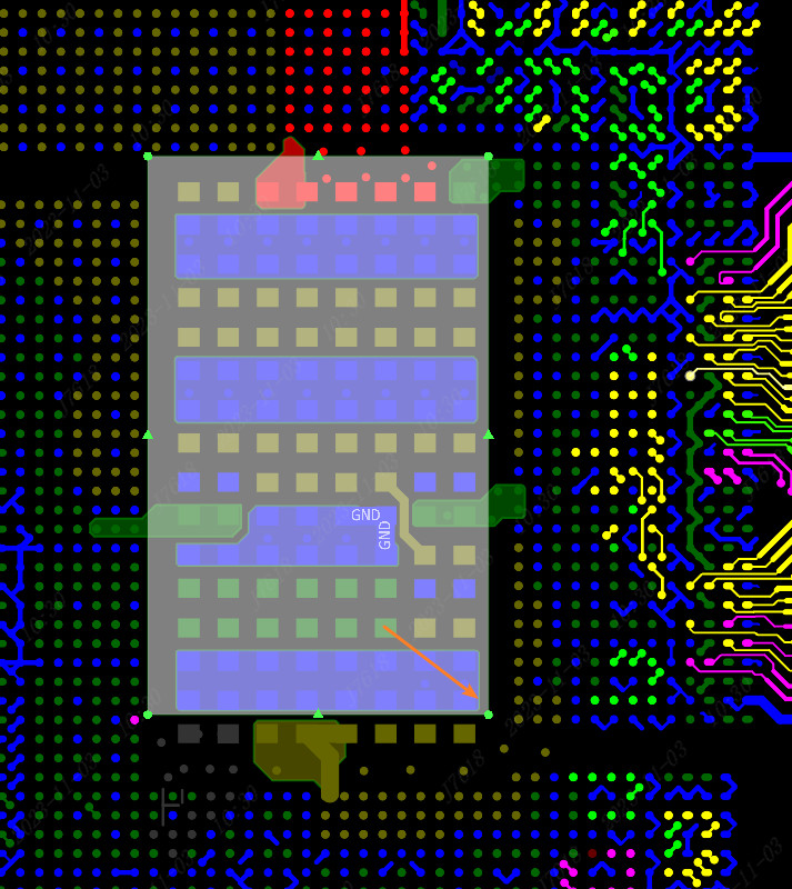
Constraint region is mostly used in PCB design containing BGA. After drawing a constraint area, special rules can be set on the area.When wiring, punching, and copper -laying operations in the area, you will interact in priority in accordance with the width, over -hole size, and spacing of the rules. When operating outside the area, according to the normal rules,。
Place the constraint area
Steps: Top menu-place-constraint region
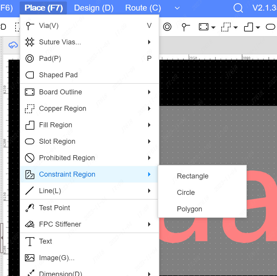
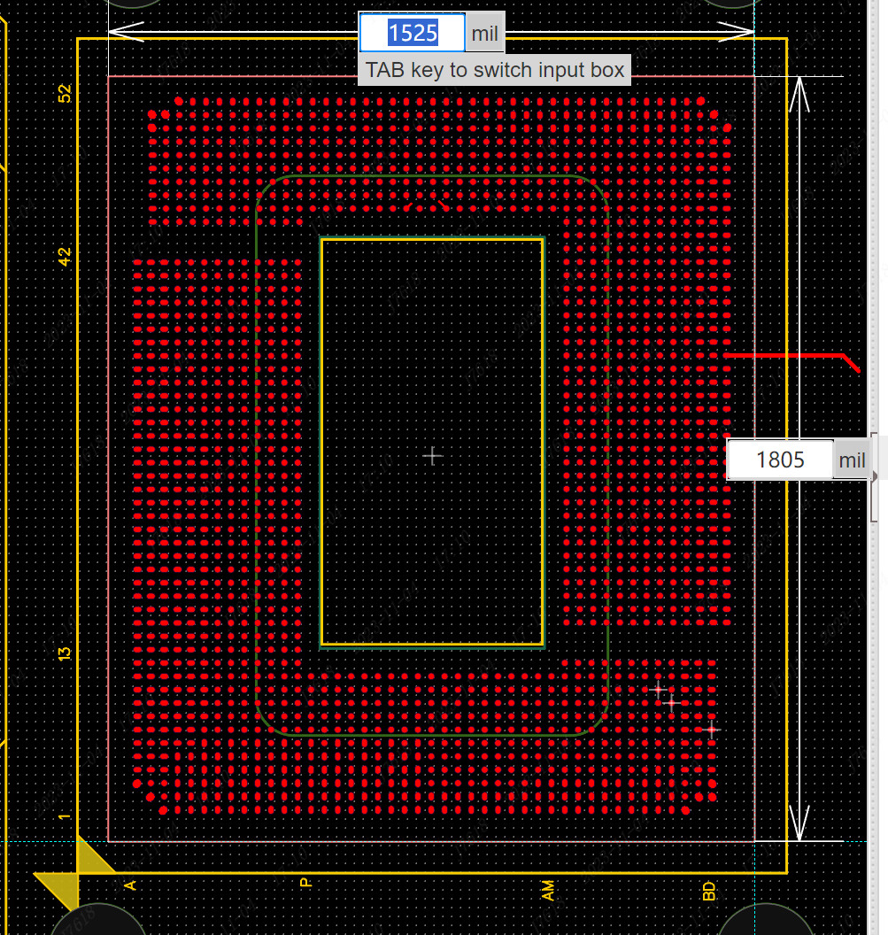
- After selecting the rectangular, circular, and polygonal shape through the top menu, the canvas enter the cursor mode, and start to draw regional shape.
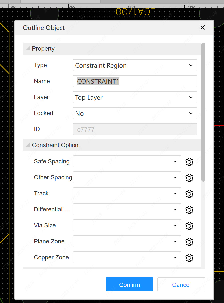
- After drawing a shape, the attribute pop -up window will appear in the constraint area. You can set the relevant attributes in advance. You can also click to confirm first, and modify it on the attribute panel.
- After the placement is completed, if the shape of the constraint area needs to be fine -tuned, you can drag the control point to adjust the control point, which is the same as the operation of the outline object such as the adjustment of the board frame.
constraint region property
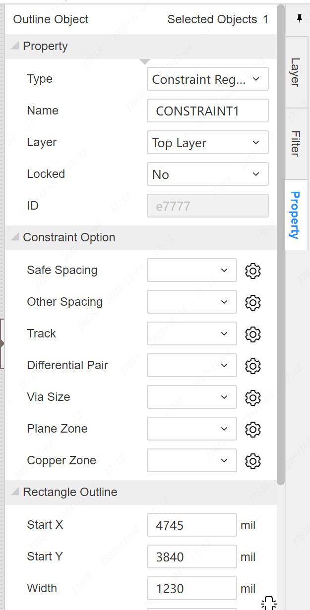
Type: The constraint area is a contour object system. Pulling can be switched to other types, such as filling areas and copper -paving areas.
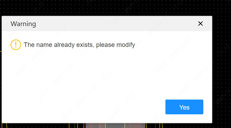
Name: The name of each constraint area is unique. This name will be used when the regional rules are allocated in the design rules.If the modified name is a already existed name, it will not be successful.
Layer: The constraint area can be set in any copper foil layer or multi -layer.When the constraint area is set in a single layer, the DRC examination will only have the rules in the restraint area of this layer; when the constraint area is set in a multi -layer, the part of all copper foil layers in the constraint area will apply the rules in the constraint area.
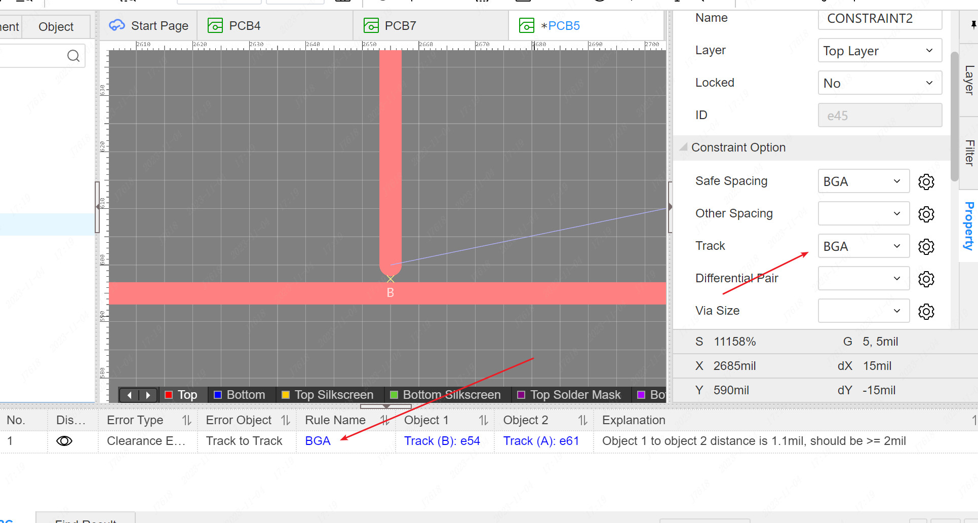
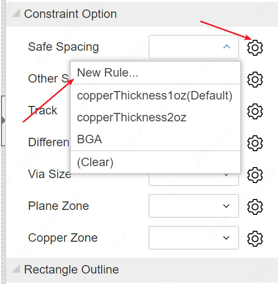
Constraint Option: In the attribute panel, you can directly pull down and switch the corresponding rules in the area. Another way is to enter the design rules dialog box for allocation.All rules are empty default. For the air, it means that there is no special rules allocated in this area, and DRC calculation is performed according to normal without rules.When a special rule needs to be assigned to the area, if a smaller rule needs to be set up, it is necessary to set up a smaller rule, and directly pull down and switch to the corresponding rules.
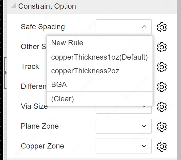
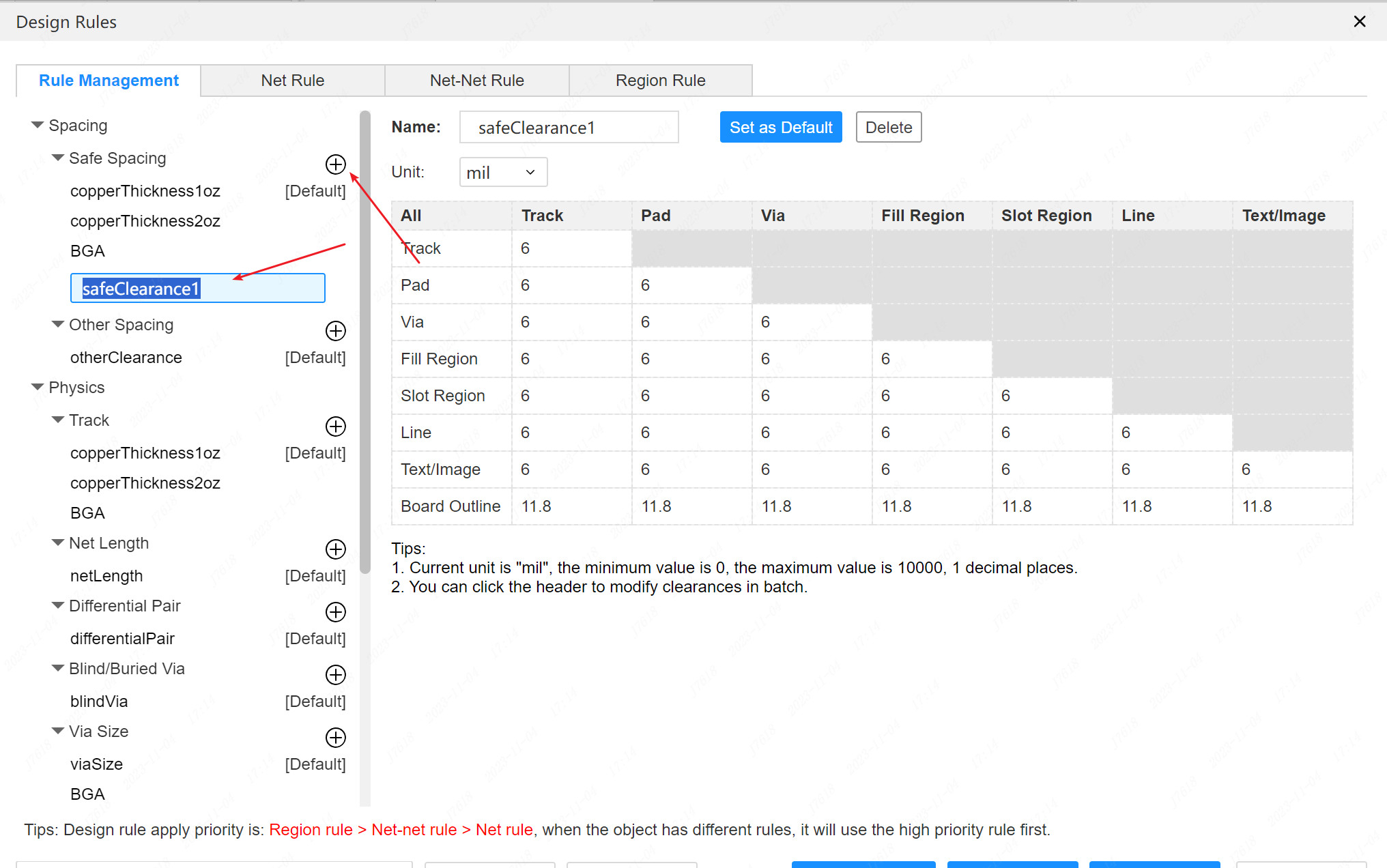
If the rules in the area have not been set in advance, you need to enter the rules management of the design rules first, and you can directly click the setting icon or drop -down option of the corresponding rules.
Constraint Region Rules
In addition to allocating the attributes of the constraint area to allocate rules in the region, you can also enter the design rules dialog box for the distribution of regional rules.
Steps: Top Menu-Design-Design Rules, the top TAB switch to region rule.
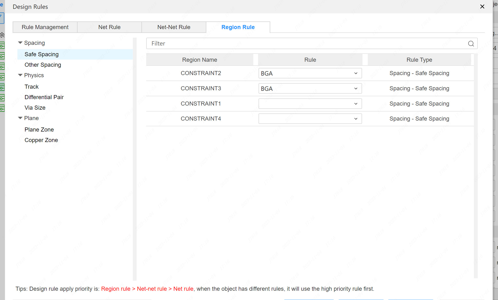
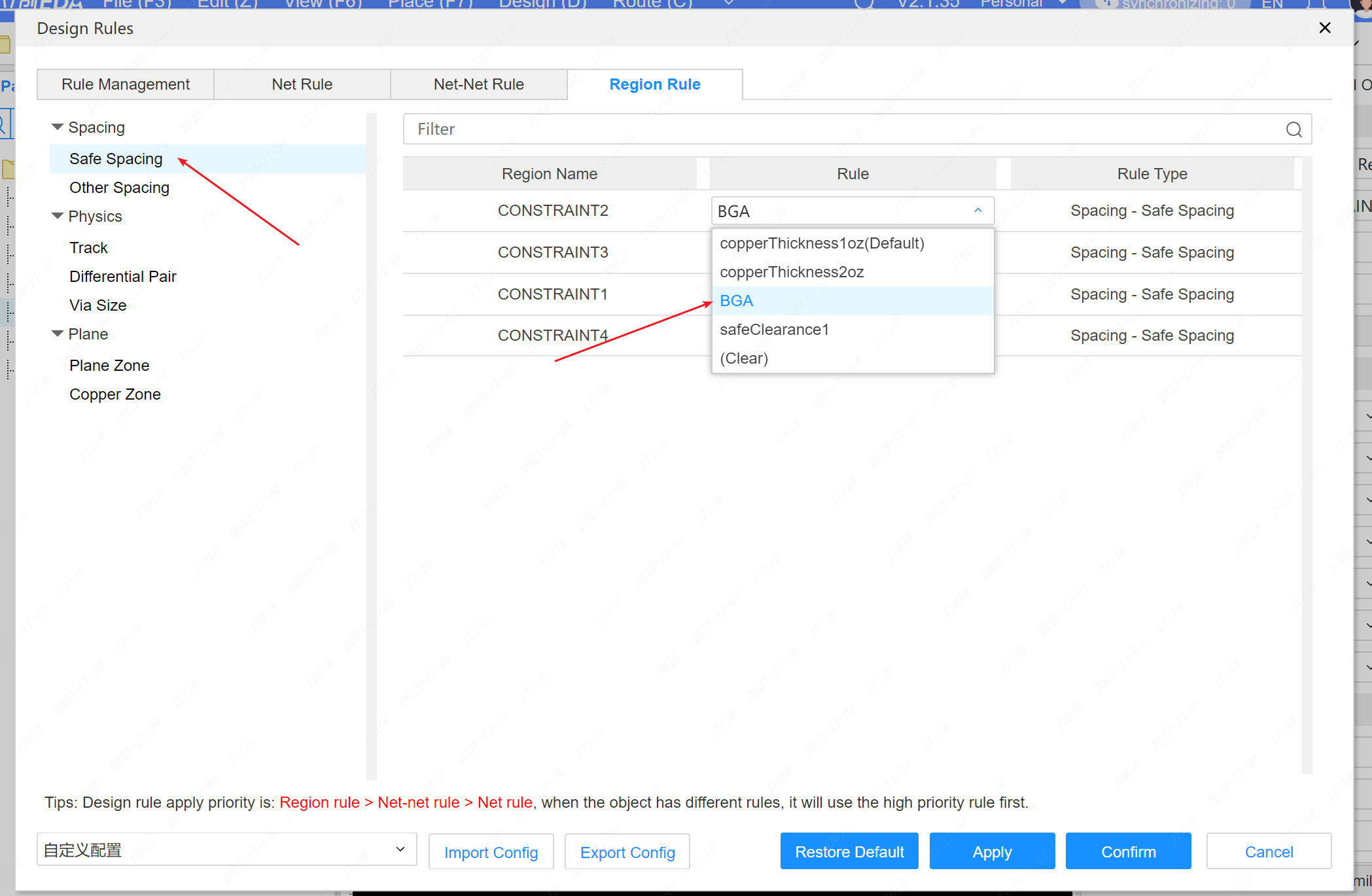
The left tree is selected by the left tree under the page, and the right side of the right side is pulled down and switching the rules for lowering different areas.
Constraint Region Interaction
Set up the rules' constraint areas, and different effects will be produced when the wiring interaction is performed.
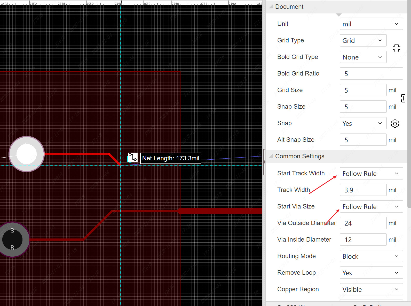
When the start width and starting size are set to follow the rules, the wiring starts from the interior of the constraint area, and will be based on the width rules, differential rules, spacing rules, over -hole size, etc. in the region, etc.The rules are qualified.
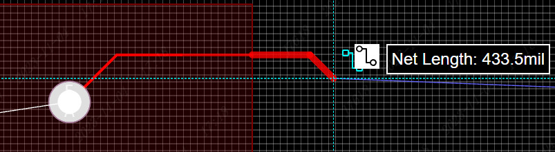
When wiring from the region to the region, or from outside the area to the region, the width rules of the inner and outer wires are different, and the width of the wire will be automatically changed in the inner and outer boundary.
Rules allocate priority: regional rules> network-network rules> network rules.
Real -time DRC and DRC inspections, paving copper, and special rules in the constraint area, will be calculated in accordance with regional rules.