Advanced Symbol Wizard
The advanced symbol wizard is used to quickly create symbols for IC type chips. The advanced symbol wizard does not distinguish the types of symbols. It only requires the user to fill in the corresponding data in the template, and the system can generate symbols according to the filled data.
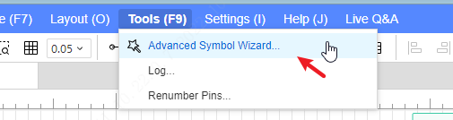
Operation steps: Top Menu - Tools - Advanced Symbol Wizard
Export the template in the template popup
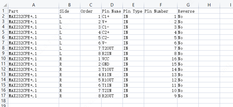
Open the template with "office" "WPS" Excel tool
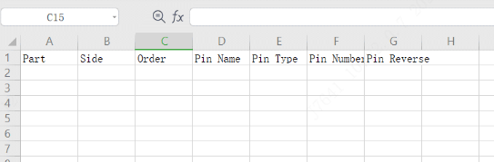
- Part: represents the sub-library page of the symbol, not the pin number;
- Side (direction): the direction of the pin, L represents the left side, T represents the upper side, R represents the right side, and B is the lower side;
- Order (serial number): Determine the positional relationship of the pins in different directions;
- Pin Name: the name of the pin;
- Pin Type: Set whether the pin is input (IN) or output (OUT) type;
- Pin Number: the number of the pin;
- Pin Reverse (non-pin): whether it is a pin type;
For example:MAX232CPE+
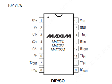
Fill in the pins information at the table:
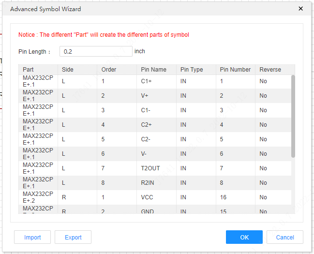
Open advanced symbol wizard, import the table
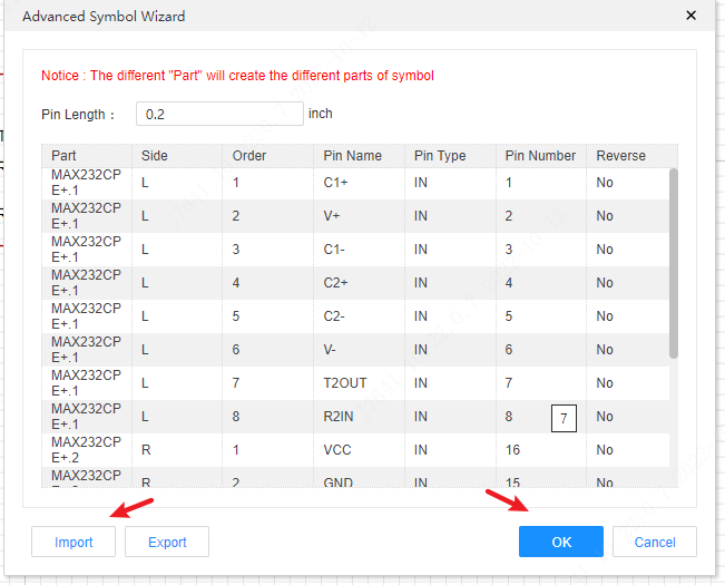
Click OK to finish wizard.
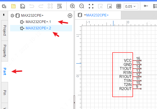
If you set different Part at the table,
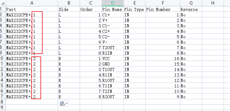
after imported, you can find and edit different parts at left hand Part tab