Personal Settings
The personal settings of EasyEDA Pro are synchronized to the server, no matter which browser you log in to, it can be automatically synchronized, reducing multiple configuration operations.
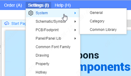
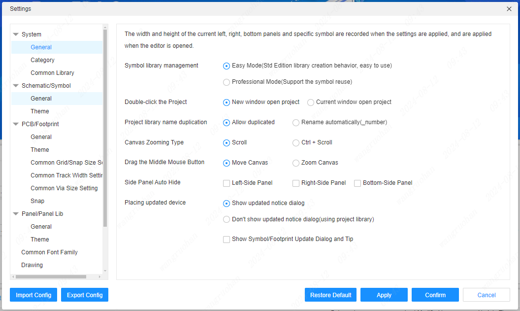
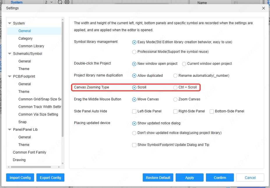
System
Canvas zoom: Default mouse wheel zoom, you can modify Ctrl + wheel zoom according to personal preference. During the drawing process, long press the right mouse button to move the canvas, and by default, click the right mouse button to cancel the drawing.
Show symbol/footprint update dialog and prompt: After checking this box, a prompt box will pop up every time a symbol or footprint is updated.
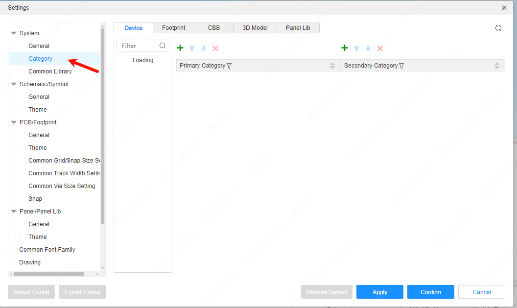
Category
Add and remove settings for device, symbol, footprint etc. Category options.
Common Libraries
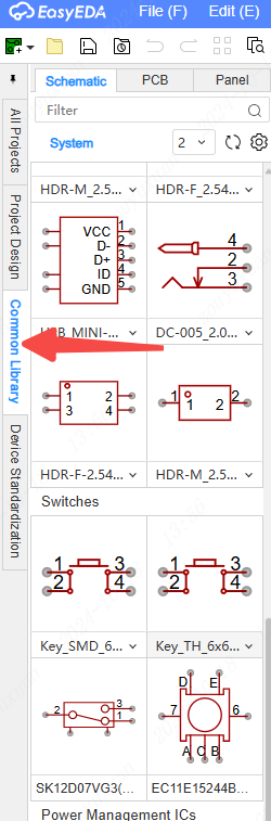
Common libraries can be configured in the schematic, PCB, and panel. They can be directly placed on the canvas through the Common Libraries tab on the left side based on your usage preferences.
On the left side, the classifications of the common libraries can be managed. By clicking the buttons, classifications can be added, moved up, moved down, or deleted. Double-clicking enables the editing of the classification names. On the right side, the libraries serving as common libraries can be managed.
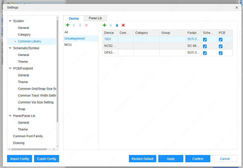
The note column will display among the names of the commonly used libraries. If the principle diagram and PCB columns are checked, the commonly used library will be shown under the corresponding document type; otherwise, it will not be displayed.
After setting combinations for the commonly used libraries, the same combinations can generate a dropdown menu under the same thumbnail.
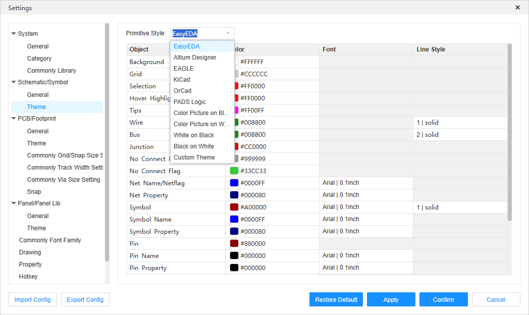
Schematic/Symbol
Some personal manipulation settings for the schematic and symbol interface.
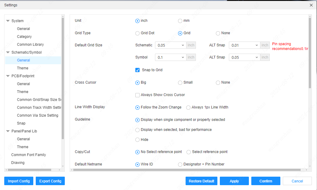
Theme
Set the schematic sheet color theme.
Support click to modify parameters such as color/stroke color, fill color, font, and line type.
PCB/footprint
Settings for the PCB and footprint drawing interface.
Theme
Drawing interface color settings for PCB and footprint interface.
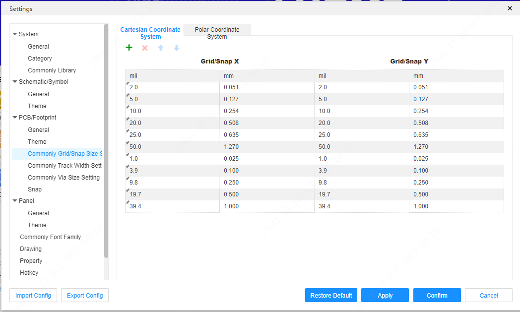
Common grid sizes
Set common sizes for PCB and footprint interface grids for easy change.
Common line width
Sets the line width settings for PCB traces.
Common via size
Sets common via settings for PCB traces.
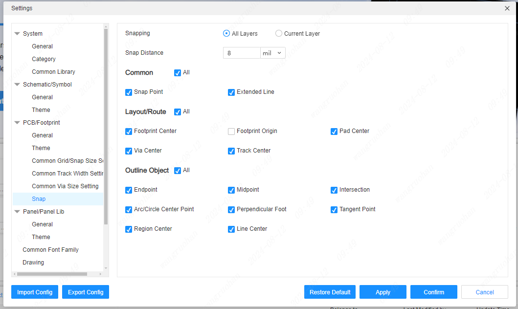
Snap
It supports a variety of adsorption settings, which can be very convenient for various adsorption.
Panel
Supports defining panel document related settings.
theme
The theme to apply when the panel document is created.
Common fonts
Support to set your own common fonts. These fonts need to be installed on the local computer before they can be called by the editor, otherwise the editor will automatically use the default font provided by the browser for rendering.
Add custom fonts:
First install the fonts you need on your local computer. If you already have fonts, you can ignore this step.
Take the Windows system as an example, find the font settings in the system settings, and get the font name.
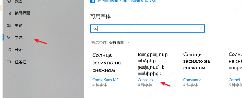
Add a font based on the font name.
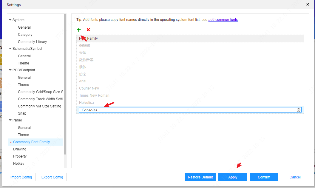
This font can be seen in the schematic or PCB text font switching, and the font switching can be performed at this time.
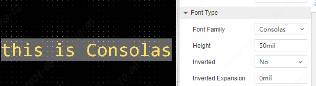
This added font can be used by schematics, panels, PCBs, etc. When the text switches fonts, you can see the new font.
Attention: 1, the editor uses the operating system native fonts, if you need to use these fonts for commercial purposes, please make sure that you have the corresponding font use copyright. It is recommended to use free open source fonts. 2, because the editor is running in the browser (including the client), when the operating system does not install the corresponding name of the font, the browser will automatically assign the default font of the current browser to display, at this time there may be the text font name is correct, but the text style is not correct.
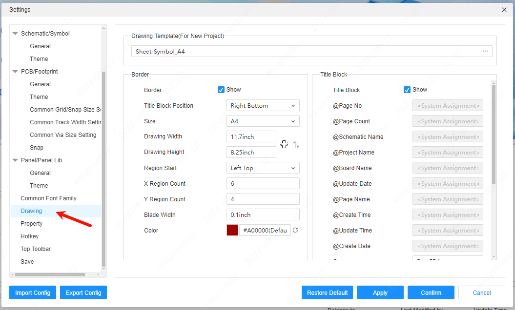
Drawings
Set the basic information of the default drawing when creating a new project.
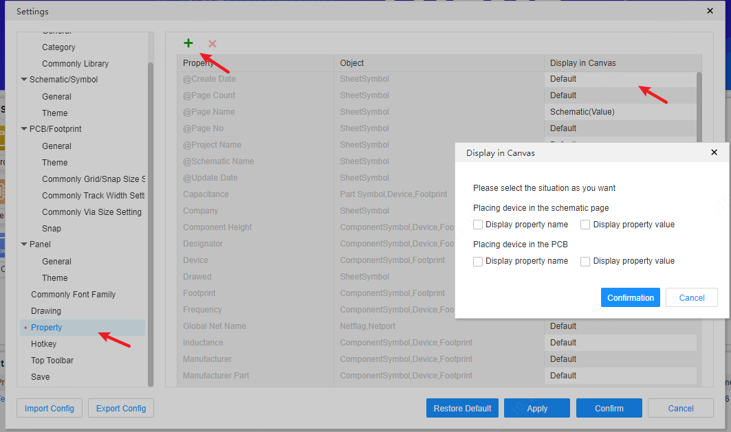
Property
Add or delete custom properties for devices, footprints, and symbols.
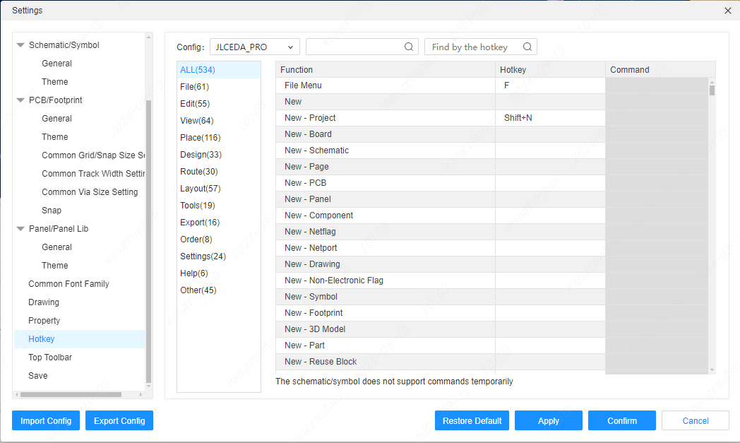
Hotkey
View and modify custom shortcut keys and commands.
Canvas
- Touchpad
The canvas is operable with the touchpad.
| Setting: Scroll Wheel Zoom | Setting: Ctrl + Scroll Wheel Zoom | ||
|---|---|---|---|
| Upward scroll of the wheel | Double-finger upward swipe | Zoom out | Upward scroll of the canvas |
| Downward scroll of the wheel | Double-finger downward swipe | Zoom in | Downward scroll of the canvas |
| Ctrl + Upward scroll of the wheel | Double-finger spread | Upward scroll of the canvas | Zoom out |
| Ctrl + Downward scroll of the wheel | Double-finger pinch | Downward scroll of the canvas | Zoom in |
| Shift + Upward scroll of the wheel | Leftward movement of the canvas | Leftward movement of the canvas | |
| Shift + Downward scroll of the wheel | Rightward movement of the canvas | Rightward movement of the canvas | |
| Leftward scroll of the wheel (Holding Shift or Alt will not be recognized) | Double-finger leftward swipe | Leftward movement of the canvas | Leftward scrolling of the canvas |
| Rightward scroll of the wheel (Holding Shift or Alt will not be recognized) | Double-finger rightward swipe | Rightward movement of the canvas | Rightward scrolling of the canvas |
The canvas scaling settings in the Settings - System menu will influence the functionality of the touchpad.
- Ctrl + Left-click and drag
When holding Ctrl and dragging an element with the left mouse button, the selected element will be attracted to the cursor. Release the left mouse button to complete the pasting. During the process, press Esc or right-click the mouse to exit the current operation.
When pasting by holding Ctrl and left-clicking and dragging, for wires, network labels, network ports, and text whose endings of names or texts are numbers, the names and text properties will be displayed and placed with a +1 suffix to the number.
Ctrl + left-click and copy-cut do not share the clipboard. That is, after dragging with Ctrl + left-click, the next paste will not become the content of the previous Ctrl + left-click drag.
- Enter for editing properties
After selecting a graphic element, pressing Enter can trigger the property function in the right-click menu, expand the right-side property panel, and focus on the key attribute input box, facilitating users to quickly edit important attributes. The shortcut key can be modified in Settings - Shortcut Keys.
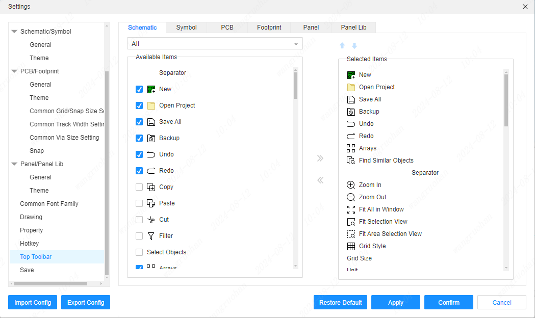
Top Toolbar
Adds and removes settings for quick Place on the top toolbar.
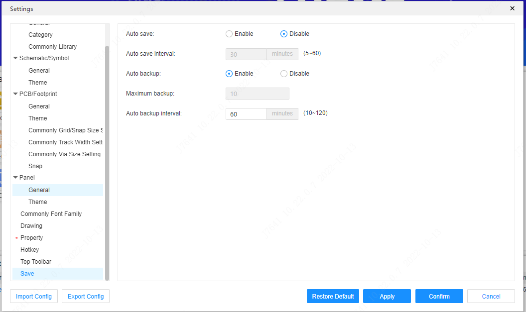
Save
You can set the automatic saving of documents, the time and quantity of saving, and the automatic backup parameter settings of the project.