Export PCB Fabrication File(Gerber)
Export method:
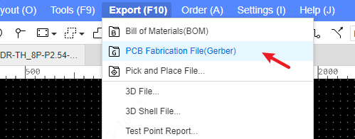
Entry: Top Menu - File - Export - PCB Fabrication File (Gerber)
or: Top Menu - Export - PCB Fabrication File (Gerber)
After clicking, the system will detect whether there are flying wires in the PCB. If so, the following pop-up window will pop up.
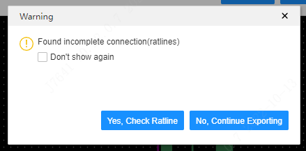
Click "Yes" to check the flying leads. It will automatically locate the first flying line, and switch to the flying line tree on the left panel to help you check. If you click "No" to continue exporting, the gerber file will be exported directly ignoring the existing flying lines.
If you don't want to automatically detect flying leads every time you export gerber, you can turn off this configuration in system settings.
Export the Gerber popup:
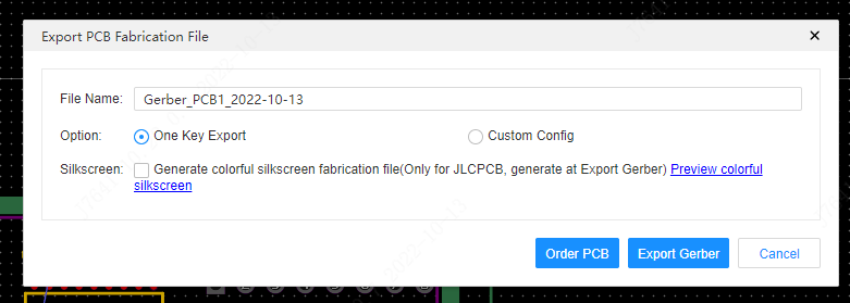
File name: Support to modify the file name and then export.
One-click export: According to the default settings, all layers and primitives are exported, excluding the drilling table and independent drilling information files.
Custom configuration: Modify the configuration according to your own needs. Support drilling information and drilling table;Support for Custom Precision: Default Integer Precision is 4 for Millimeters and 5 for Inches, with Adjustable Decimal Precision; support adding different configurations on the left list; support selecting exported layers; layer mirroring; support selecting exported primitives. When exporting, select a configuration for Gerber export. Up to 20 configurations can be created, double-click to modify the configuration name.
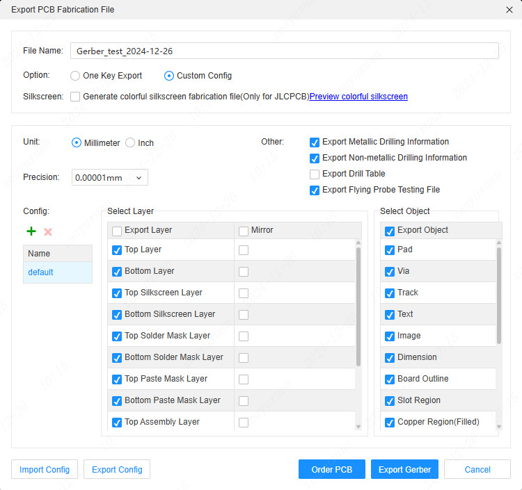
Unit: The unit of the exported Gerber file and drilling file, the default is mm.
Format: The numerical format of the exported drilling file, the number of integer digits and decimal digits, affects the expression of numerical precision. This setting may affect the alignment of the drill file viewed by the Gerber Viewer. If the Gerber viewer previews the Gerber and drilling files and finds that the drilling files are inaccurate, you can reset the numerical format of the drilling files in the Gerber viewing tool to 3:3, or other formats.
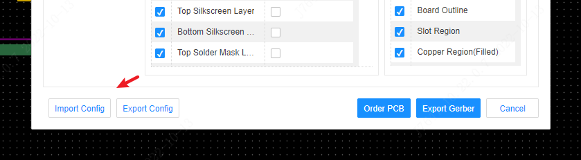
Export/Import Configuration: Supports importing and exporting Gerber custom configurations, which is convenient for configuration reuse. Configuration information is stored in personal preferences for cloud synchronization.
Gerber Instructions
Gerber compressed package: After exporting Gerber, it is a zip compressed package, which can be directly uploaded when the board factory places an order. Those with editing needs (such as CAM engineers) can use third-party CAM tools to edit Gerber after decompression. Description of file names in Gerber:
Gerber filename:
The generated Gerber file is a compressed package. After decompression, you can see the following files:
| File Name | Type | Remarks/Description |
|---|---|---|
| Gerber_BoardOutline.GKO | Outline file | The PCB board factory cuts the shape of the board according to this file, and the digging area drawn by EasyEDA is reflected in the outline file after Gerber is generated |
| Gerber_TopLayer.GTL | PCB Top Layer | Top Copper Foil Layer |
| Gerber_BottomLayer.GBL | PCB bottom layer | Bottom copper foil layer |
| Gerber_InnerLayer1.G1 | Inner Copper Foil Layer | Signal Layer Type |
| Gerber_InnerLayer2.G2 | Inner copper foil layer | The inner layer of the inner layer type is positive when outputting, and negative when PCB is drawn (the drawn lines are not outputted in Gerber). Note: V2.2.33 version and before use GP + digital suffix to represent the inner layer, and then avoid conflict with the inner suffix of other EDA negative methods, and change it to G + digital method |
| Gerber_TopSilkLayer.GTO | Top silkscreen layer | |
| Gerber_BottomSilkLayer.GBO* | Bottom silkscreen layer | |
| Gerber_TopSolderMaskLayer.GTS | Top Solder Mask Layer | It can also be called the copper expose layer. By default, the board is covered with oil, and the elements drawn on this layer correspond to the area of the top layer, which is not covered with oil |
| Gerber_BottomSolderMaskLayer.GBS | Bottom Solder Mask | It can also be called the copper expose layer. The board is covered with oil by default, and the elements drawn on this layer correspond to the area of the bottom layer without oil |
| Gerber_TopPasteMaskLayer.GTP | Top layer flux layer | For stencil fabrication |
| Gerber_BottomPasteMaskLayer.GBP | Bottom layer of soldering flux | For stencil fabrication |
| Gerber_TopAssemblyLayer.GTA | Top assembly layer | Only for reading, does not affect PCB manufacturing |
| Gerber_BottomAssemblyLayer.GBA | Bottom assembly layer | Only for reading, does not affect PCB manufacturing |
| Gerber_MechanicalLayer.GME | Mechanical Layer | The information recorded in the mechanical layer in the PCB design is only used for information recording. The shape of this layer is not used for manufacturing by default during production. This layer is only used for text identification. For example: process parameters, V-cut path, etc. |
| Gerber_DocumentLayer.GDL | Document Layer | Used to record PCB remarks, not involved in manufacturing |
| Gerber_CustomLayer1.GCL | User-defined layer | User-defined layer generally does not belong to the layer required for generation. If you need to use it in production, you can communicate with the board factory |
| Gerber_DrillDrawingLayer.GDD | Drilling layer | This layer does not participate in manufacturing, it is used for comparison and identification of the position of the generated via hole |
| Gerber_TopStiffenerLayer_xx_xx.GTSL | Top Stiffener Layer | This file is stiffener object layer, only for JLCPCB use |
| Gerber_BottomStiffenerLayer_xx_xx.GBSL | Bottom Stiffener Layer | This file is stiffener object layer, only for JLCPCB use |
| Drill_PTH_Through.DRL | Drilling layer for metallized multilayer pads | This file shows the drill hole position that needs metallization on the inner wall, such as multi-layer pads and through-hole vias |
| Drill_PTH_Through_Via.DRL | Drilling layer of metallized through-hole type via | This file shows the drill hole position that needs metallization on the inner wall. This file use at JLCPCB |
| Drill_PTH_Inner1_to_Inner2.DRL | Drilling Layer for Metallized Blind and Buried Via | This file shows the position of the drill holes that need metallization on the inner wall. Inner1 and Inner2 are automatically changed according to the layer type of the blind and buried via |
| Drill_NPTH_Through.DRL | Non-metallized drilling layer | This file shows the drilling position where the inner wall does not need metallization, such as through holes (circular trenching areas) |
| Fabrication_ColorfulTopSilkscreen.FCTS | Top layer color silkscreen file | This file only exists when the color silkscreen process is checked when exporting Gerber |
| Fabrication_ColorfulBottomSilkscreen.FCBS | Bottom color silkscreen file | This file only exists when the color silkscreen process is checked when exporting Gerber |
| Fabrication_ColorfulBoardOutLineMark | Color silk screen Mark file | for JLCPCB use only. This file is available only when color silkscreen printing process is selected when exporting Gerber |
| Fabrication_ColorfulBoardOutlinelayer.FCBO | colorful silkscreen printing board outline layer file | JLCPCB use only, This file is available only when colorful silkscreen printing process is selected when exporting Gerber |
| jlcpcb.json | Gerber configuration file | is used only to store some additional order information. For example, the position of the reinforcing plate |
| FlyingProbeTesting.json | JLCPCB flying probe testing file | used only by JLCPCB to store the flying probe test information for convenience of flying test |
Notice:
- _Before generating a manufacturing file, be sure to do a 2D or 3D preview to check the Design Manager's DRC error entry to avoid generating defective Gerber files. _
- The generated Gerber is generated by the browser, so it must be downloaded through the browser's own download function, and cannot use any third-party downloader
- The coordinates of the Gerber file follow the canvas coordinates
- When exporting Gerber, the default coordinate format precision for drilling files (integer bits: decimal bits) is 3:5 for mm and 2:6 for inch. If the size exceeds the range, it will automatically use the 4:2 format. If you find drilling offsets in viewing tools such as CAM350, you can adjust the drilling coordinate format (usually mm 3:3, inch 2:4). You can also choose custom output when exporting and set the format precision.
- The circular slot region of EasyEDA, when the diameter is less than or equal to 6.5mm, the Gerber output to NPTH drilling file, and the circular slot region greater than 6.5mm and the slot region of other shapes are reflected in the board outline GKO file in Gerber.
Gerber Preview
Before sending the Gerber file to the manufacturer, use the Gerber Viewer to double-check that the Gerber meets the design requirements and has no design flaws.
Gerber viewers include: Gerbv, FlatCAM, CAM350, ViewMate, GerberLogix and some DFM inspection tools.
Recommended free Gerbv:
Official website homepage: http://gerbv.geda-project.org/ Download address: https://sourceforge.net/projects/gerbv/files/ Download address 2: Gerbv-2.6.0.exe
How to use Gerbv:
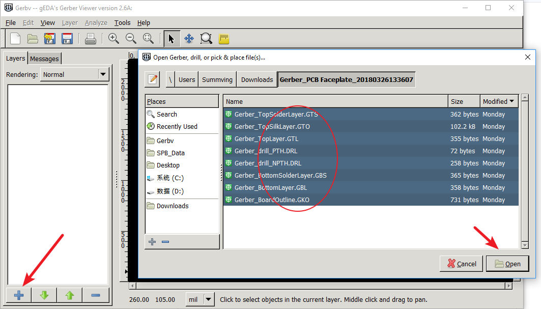
Download Gerbv, and open it; unzip the downloaded Gerber archive.
Click the plus sign
+in the lower left corner to open the Gerber folder, and SHIFT+select all or CTRL+A select all the unzipped Gerber file.
- Then zoom, measure, change layers, check whether drilling, copper plating, etc. meet the design and production requirements.
Other free Gerber preview tools: