Editor
THIS TUTORIAL IS TRANSLATING BY GOOGLE, WILL CORRECT IT CONTINUOUS
EasyEDA Pro Vs EasyEDA Std
EasyEDA is currently available in two editions, EasyEDA Professional and EasyEDA Standard. The Standard Edition is geared towards students and education, with simpler features and usage; the Professional Edition is geared towards enterprises and teams, with more powerful features and higher constraints.
For specific functional differences, please see:EasyEDA Edition Comparison
Tutorials Download/Video Tutorials
PDF Tutorials Download:https://easyeda.com/page/download
Preparation
No graphics card or low performance graphics card when running the editor
When the computer does not support WebGL, this message will pop up because the PCB needs to use graphics acceleration (WebGL engine), otherwise the PCB will not run properly. Usually computers and graphics cards from 2015 onwards are supported.
Please try the following. 1, please use the latest Google or Firefox browser, in the browser settings to enable hardware acceleration. 2, update the graphics card driver to the latest version. 3、If still prompted, please add the graphics display of the browser to the graphics acceleration list in the graphics setting software. 4、If the above operation is invalid, you need to update your device, your computer may not support WebGL. 5、Or please use the standard edition of EasyEDA.
Recommended computer configuration: post-2017 computer and graphics card, CPU i5, 8GB of RAM, 1080P display.
The current browser environment does not support running EasyEDA Pro
Because EasyEDA Pro uses indexedDB technology, if your browser does not support it, you will get this message.
1、Please use the latest Google or Firefox browser 2、If you are using Firefox, please do not open the editor in incognito mode (anonymous mode) 3、If you can do it before, please restart the browser or client, if the client restart is invalid, please download the latest version to install.
Library
How to create a library file
1、In the editor home page, click New Device. 2, device binding symbol and footprint, if there is no symbol and footprint, you need to create a new one first. 3、After the completion of New, in the bottom panel (shortcut key S), or in the device Place dialog box (shortcut key SHIFT+F) to find the device list, select the device to place in the schematic.
How EasyEDA's component libraries are differentiated
EasyEDA Pro's libraries are divided into: device library, symbol library, footprint library, and reuse block library. Device = Symbol + footprint + 3D model + Properties. It is possible to reuse symbols, footprints, 3D libraries, etc. very well. New devices need to be associated with symbols footprints, etc.
Only support placing device in schematic or PCB, when the device is placed in schematic, it will take symbol with it and instantiated as component at this time. The device on the canvas is a component.
Schematic
How to modify the size of the drawing
In the properties panel on the right, click "Drawing Symbols" and select other sizes of drawing symbols.
Specific reference.
Project Drawing Setting:https://prodocs.easyeda.com/en/schematic/design-project-drawing-setting/index.html
Drawing Symbol Creation:https://prodocs.easyeda.com/en/symbol/file-new-symbol-drawing-symbol/index.html
How come my updated library is still old when I place it again?
EasyEDA Pro Professional supports the concept of a project library. The placed library will automatically enter the project library as a template, and the next time you place a library from the same source will give priority to the template inside the project library, avoiding the update of individual libraries to affect the existing design of the project.
The project library can be edited, the entrance is: bottom panel - Component Library - Project - Device/Symbol/Footprint.
You can also update the project library directly, the entrance is: Top Menu - Design - Update Symbols/Devices
Please refer:https://prodocs.easyeda.com/en/schematic/side-bottom-panel-project-library/index.html
How to place net labels
EasyEDA Pro Professional no longer supports separate net labels like the standard version, the Professional version's Place net labels (shortcut N) actually automatically sets the name for the wire. Please draw the wire and then set a name attribute to the wire, the wire name is the network name. You can also create a network by placing a net labels one the wire.
How to add a horizontal line above a network name
Enter a wavy number at the top of the wire's network name, e.g. ~VSS.
If you need a network name with and without an upper horizontal line, enter a wave again, e.g. ~VSS~/GND, then VSS has an upper horizontal line above it and no slash after it.
The same is true for symbolic pin names.
How to create a hierarchy schematic
In the top menu - Place - Reuse Blocks, enter the name of the block, when finished, right click on the selected block and expand it, at this time you can place ports, device symbols, etc. Then create the pin information of the Reuse block symbols, etc. by using the: Top menu - Design - Update Block Symbols. After creation, you can switch to the project library in the bottom panel (shortcut S to open) and switch to the Reuse blocks for Place in the schematic.
Multi-level nested hierarchical diagrams can be supported.
How to batch rotate the circuit
When the batch selection circuit has included wires, the whole rotation is not allowed. Press the space bar to rotate when the wires are not included.
How to create multiple sub projects in a project
In the top menu - New - Board, a new board, schematic, PCB will be created automatically, at which point multiple board designs can be supported.
PCB
Cannot open PCB properly
1, please ensure that the computer has a graphics card, and not very old graphics card. Because opening the PCB needs the support of the graphics card. 2, re-open the editor to try or log out (choose to remove the cache), if you still can not open, there may be data abnormalities, please contact technical support. 3, if the client, please use Google Chrome and start hardware acceleration. Currently found that some Win7 computer installation client can not properly open PCB, the browser is normal.
How to set design rules
In the top menu - Design - Design Rules
How to generate PCB order file
In the Top Menu - Export - PCB Fabrication File Gerber
How to modify the copper zone heat welding
Just modify the rules for copper zone in the design rules.
How to show hidden copper
In the Filter tab on the right side, hide the "Copper Pavement Area (Fill)". Or click on the copper pavement and right-click to hide it. Shortcut SHIFT + M to show or hide all.
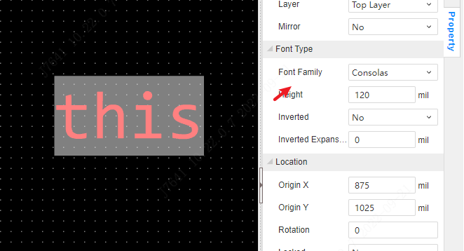
Add commonly used fonts
Support setting your own commonly used fonts. These fonts need to be installed on the local computer to be called by the editor, otherwise the editor will automatically use the default font provided by the browser for rendering.
To add custom fonts. (1) Install the fonts you need on your local computer first, if you already have fonts, you can ignore this step.
(2) Take Windows system as an example, find the font settings inside the system settings and get the font name. You need to get the exact display name, not the file name of the font file. 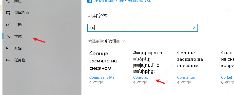
(3) Add a font according to the font name. 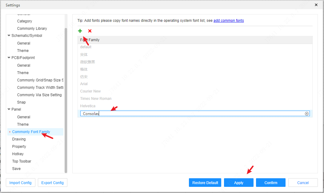
(4) You can see this font in the text font switch of the schematic or PCB, and you can switch the font at this time.
The added fonts can be used by schematics, panels, PCBs, etc.
Import
How to import files from EasyEDA Pro Standard Edition
Details
1、Open the Professional Edition, click the "Migrate Standard Edition" icon on the start page to import the files of the Standard Edition.
2、When the project is not opened in the Professional Edition, first in EasyEDA Pro Standard Edition - Project List - Right click - Download Project, then in EasyEDA Pro Professional Edition - Import EasyEDA Pro (Standard Edition), select ZIP archive to import.
If it is a library file, then in EasyEDA Pro Standard Edition first export EasyEDA Pro format, and then import can be. When importing the schematic library, you can choose whether to generate devices or symbols, or both when importing.
Note: If there is a PCB, please make sure to import the schematic and PCB together after compression.
3, in the professional version of the project has been opened, you can choose to import EasyEDA Pro standard version of a single JSON file, the import will be inserted in the current open project.
How to import AltiumDesigner or Protel or Kicad files
How to delete project files in offline mode?
Details
You need to select the folder and click the right mouse button to enter the path directory, then delete it inside the path directory, and finally go back to Edit to refresh it. 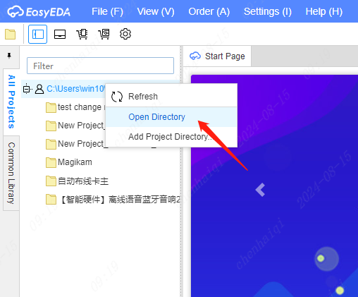
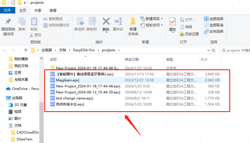
How to open eprj and epro files?
Details
Firstly eprj files are offline files and must be opened in offline mode. The epro file is an eda exclusive file, which can also be called an online file, and it can be opened in both offline and online modes. All that is required to open an eprj file is that your computer has easyeda installed, and double-clicking on the file will automatically open it. To open the epro file, you need to use the import tool.This tool can be found in the top menu bar. 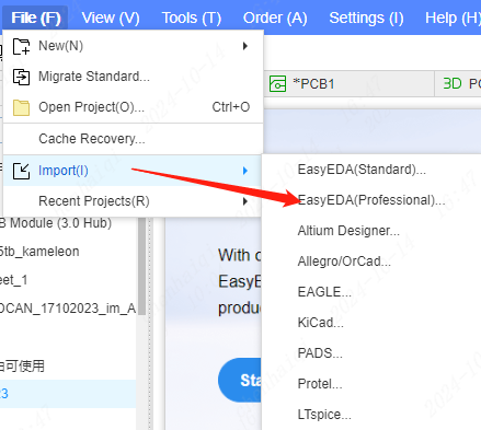
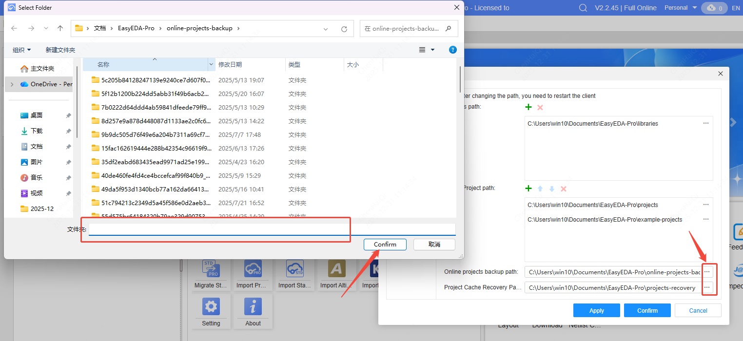
How do I change the file save path?
Details
You can find the function to save data paths in the top right menu bar. After opening the settings, you can see different file save paths, where all your file data and backup data are located.You can add, delete, or replace them. 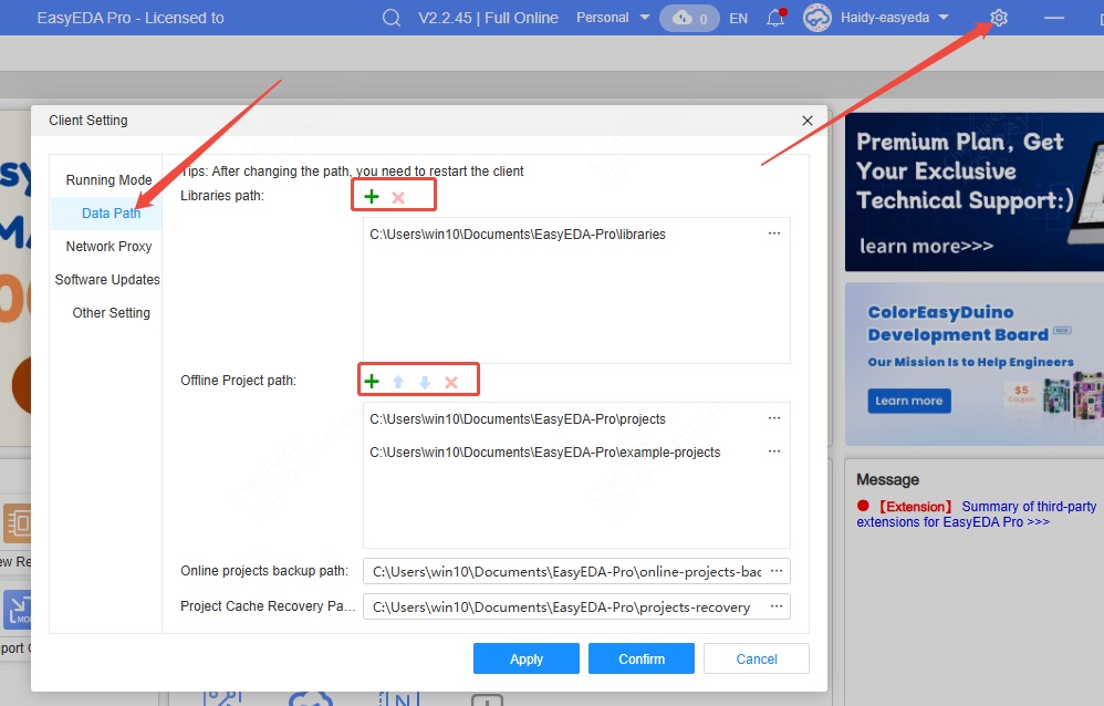
What should I do if I forget my password?
Details
If you forget your password, click "Forgot Password" on the login screen. Follow the prompts to retrieve your password. The prerequisite is that you must remember your account email address. 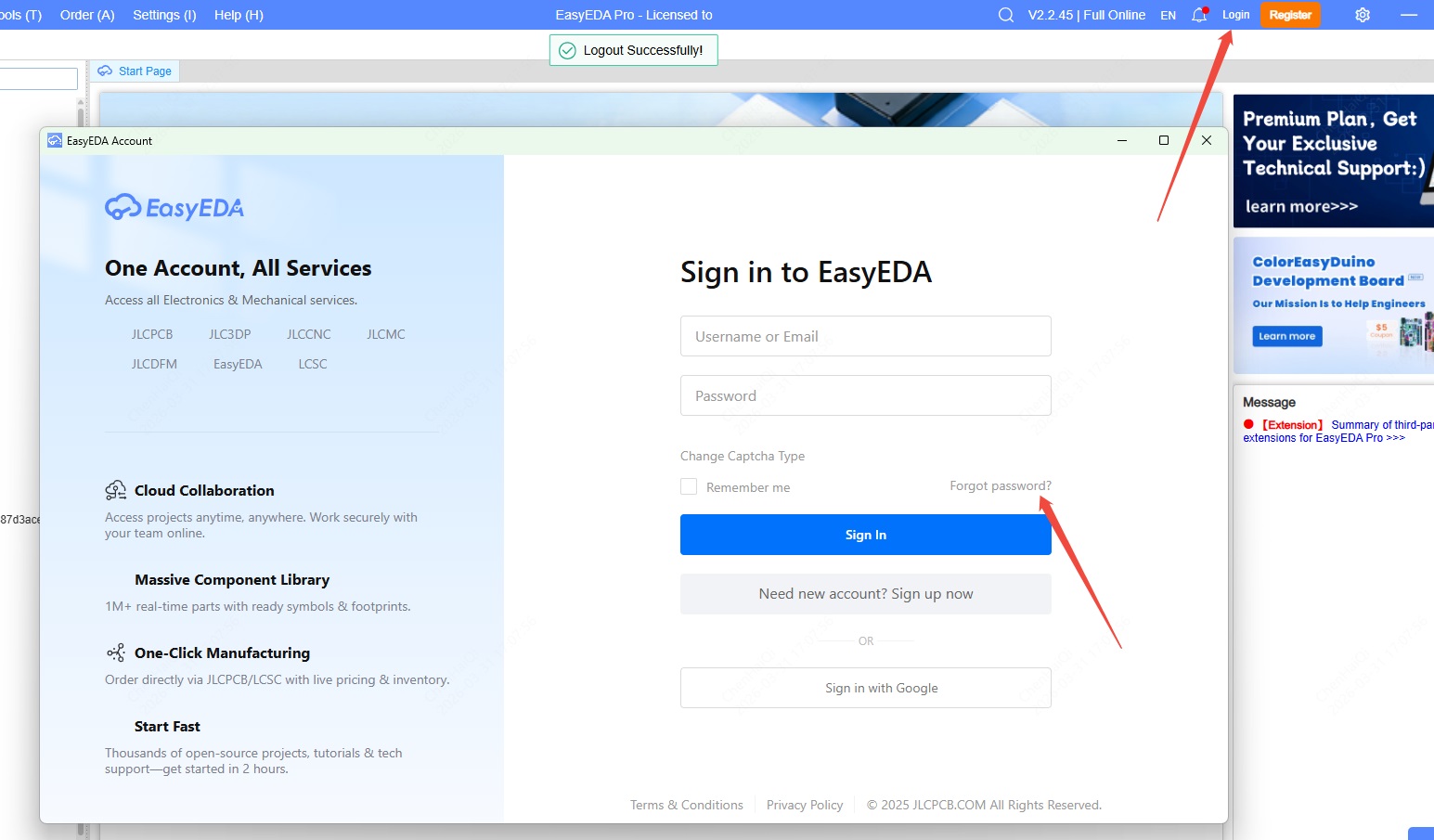
How do I change the login verification method?
Details
We offer two login verification methods, which you can switch between. You can click here to change to a different verification method. 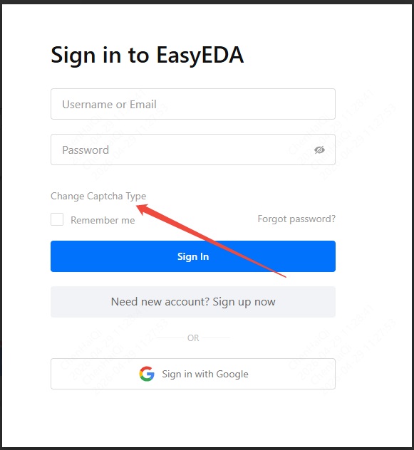
How to enable dark mode in the editor?
Details
Dark mode was introduced in version V3. You can find it in the editor's settings.We also provided a "Follow System" setting. This means that if your browser or computer is set to dark mode, the EDA editor will automatically follow suit. 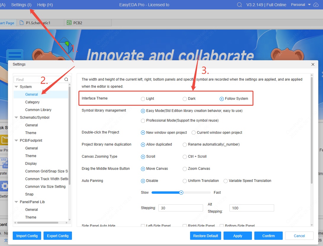
How to record a video and send it to technical support?
Details
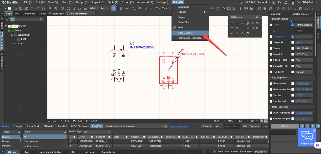
Our software comes with a built-in video recording tool, allowing users to record their operations and send them to technical support for evaluation. 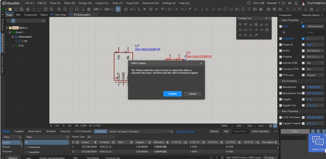
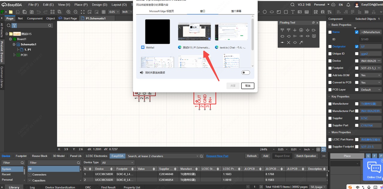
Simply select the correct window to record and save the video to your local device.
How to create a Node?
Details
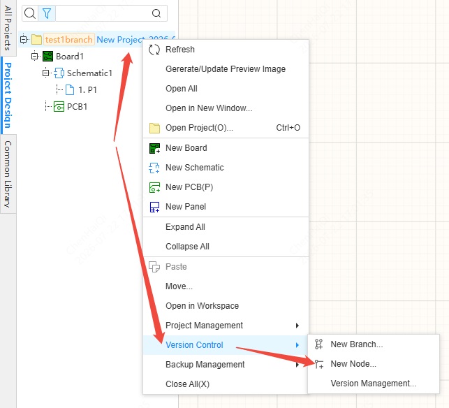
A Node represents a saved version of a project and is used to linearly record modifications. The "New Node" tool is located within "Version Control", while the "Version Control" tool can be found in the top menu bar or by right-clicking on the selected project file.(Clicking on the board, schematic, or PCB has no effect) 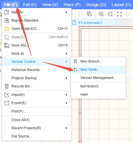
Enter the node name and description. Node names can only consist of letters, numbers, and dots. 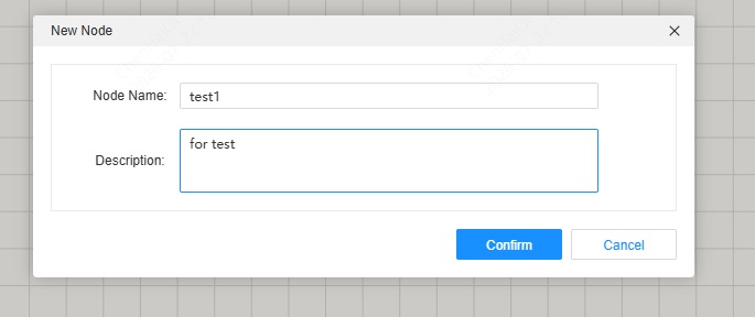
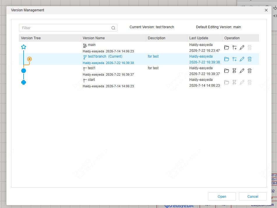
After creation, you need to view it in "Version Management". 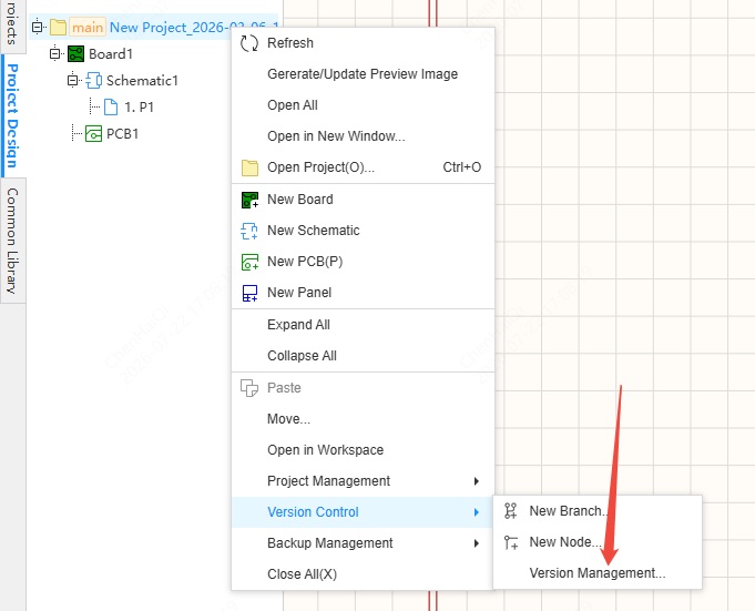
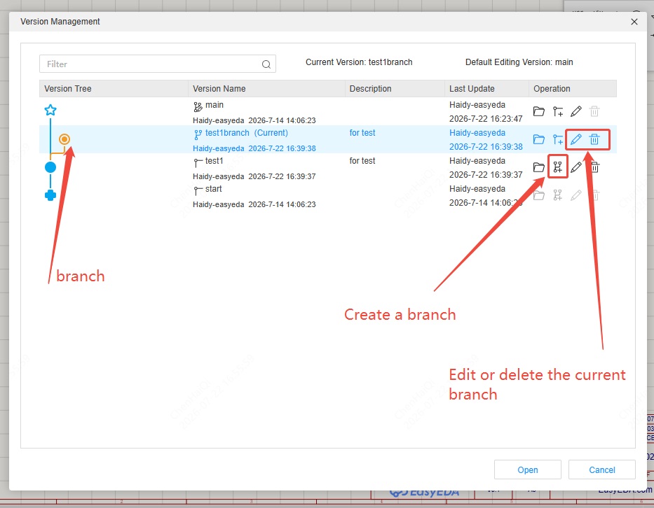
Nodes are marked with solid circles and support opening in a new window, creating branches, editing names, editing descriptions, and deleting operations. 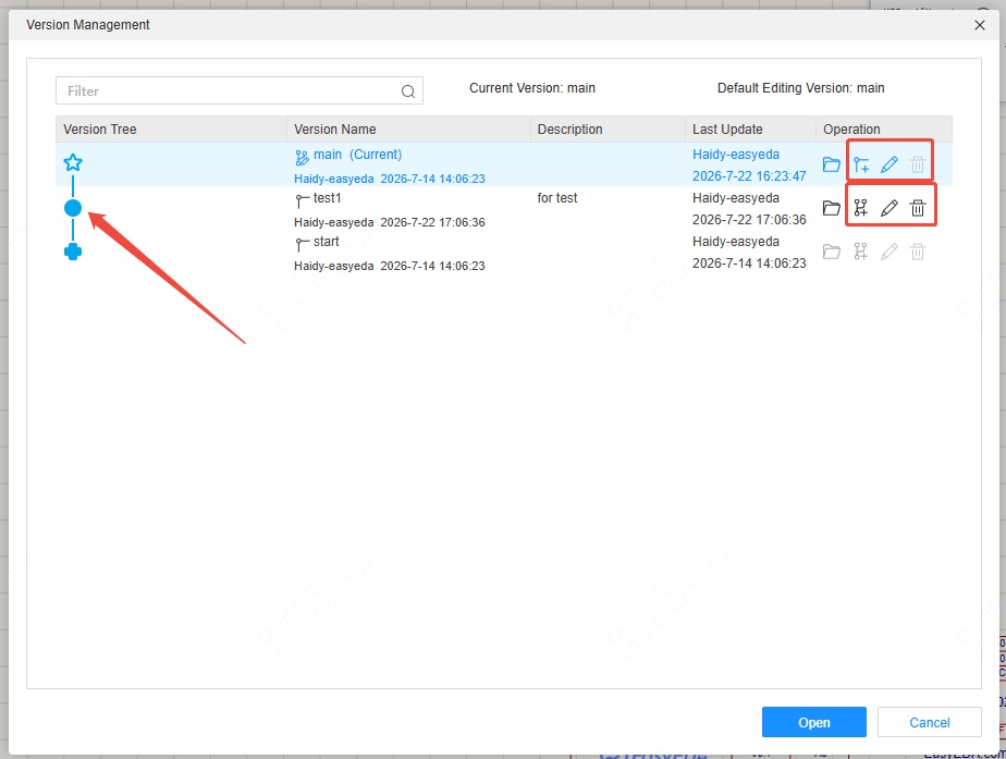
Nodes can be opened and viewed in a new window, but editing is not supported. The currently opened node name will be displayed next to the project name in the document tree on the left. 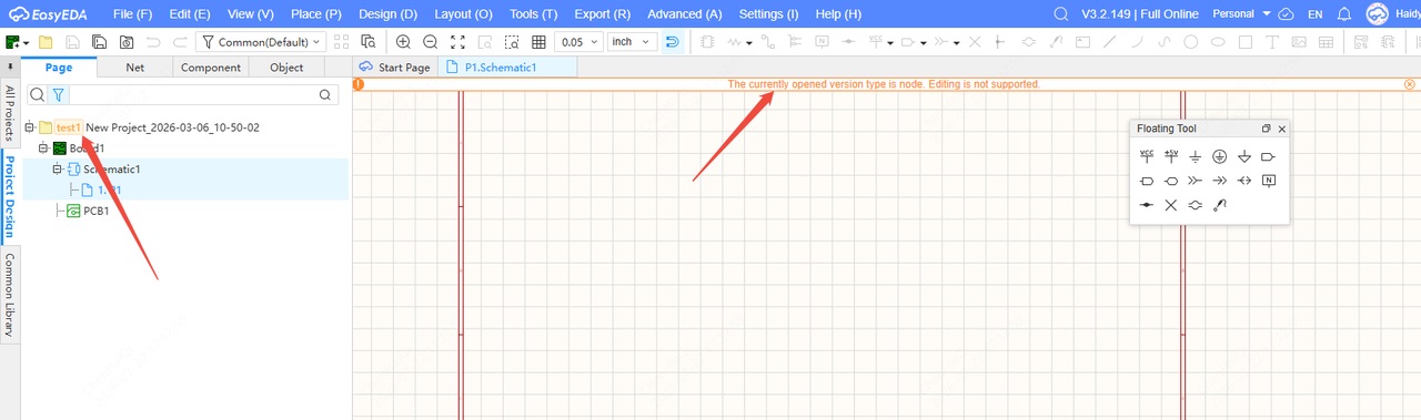
Extras: This mark is the initial point (start) of all versions. The identifier is a solid cross. It will exist whenever the project is created and cannot be deleted. 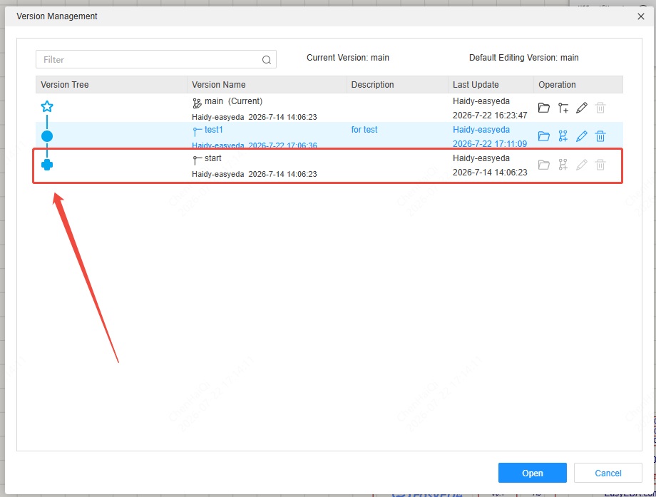
This sign is the default editing branch. It is the editable version that is opened by default when the project is opened. The identifier is a hollow five-pointed star, and the default name is "main". It supports modification and replacement. 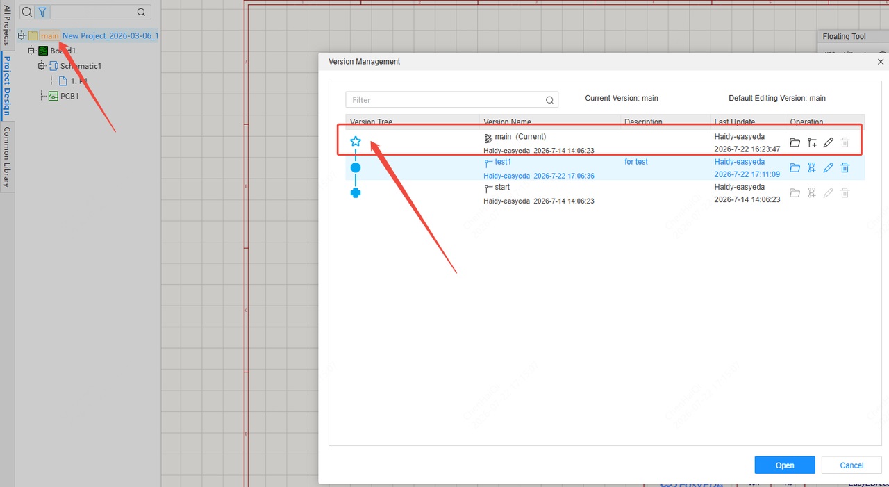
How to create a branch?
Details
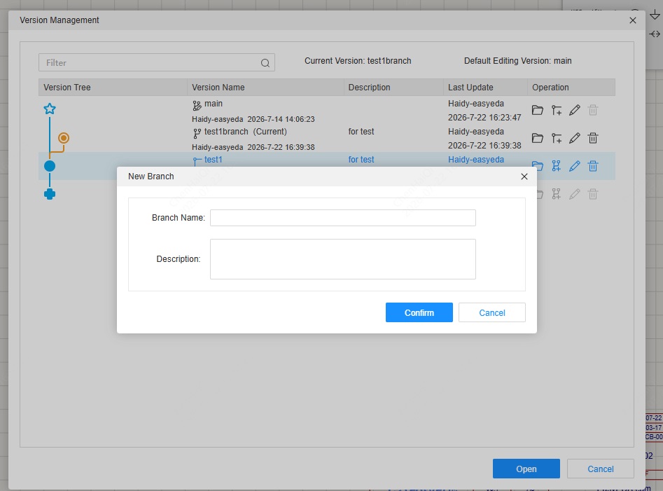
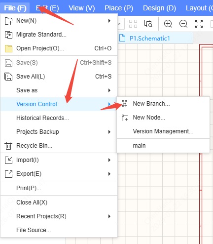
Branches are used for parallel development of different features or for iteration, allowing modifications to be made independently of the main branch. When a project requires significant changes and iterations, users can create branches at nodes and maintain different versions of the project on different branches. The "New Branch" tool is located within version control, while the "Version Control" tool can be found in the top menu bar or by right-clicking on the selected project file.(Clicking on the board, schematic, or PCB has no effect) 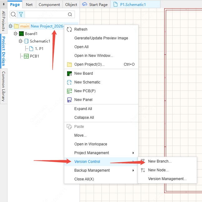
When creating a branch quickly, if the current version is a branch, a new node must be created first. (Branch Name can only include letters, numbers, Chinese characterss, and dots.Branch Name must be between 2 and 30 characters) 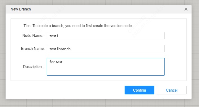
Once created, you can open this branch.Branches support editing. 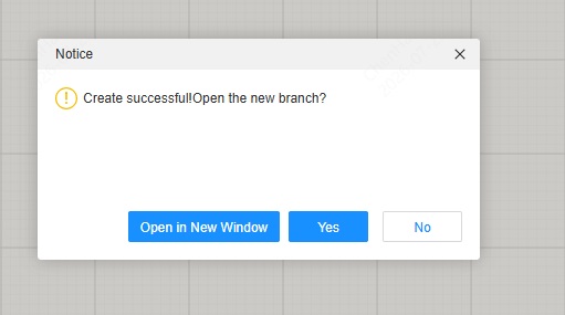
After you've created it, you can view it in "Version Management". 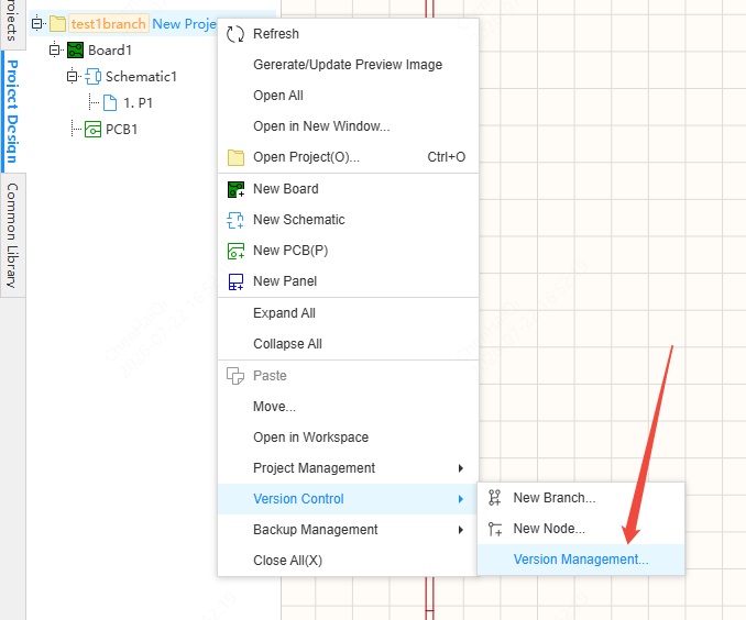
You can also create or enter the editing interface here.