Left Panel - Nets
The left panel on the PCB interface-the network display the network of the current PCB interface, which is divided into nets, net class, ratlines, differential pair, equal length groups, pads pair group.
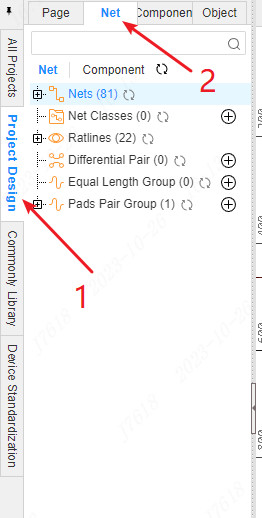
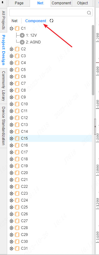
Switch the tag to the component above will display the network of pads in the current PCB
Net
Display the number of networks and specific networks in the current PCB interface,Among them, the empty network will also display, the name is None.
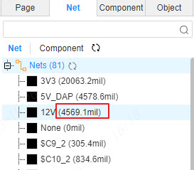
Network positioning: Click the network to light up in the PCB interface and translate to the center.
Double -click the network after the canvas and highlight it in PCB.
Network color:Set the network color: Click the color cubes in front of the network name to open the color setting panel and set the demonstration you need.
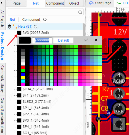
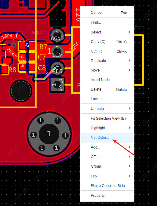
You can also right -click the color to set the color
Network length:The parentheses behind the network name are the length of the current network. The unit follows the canvas unit. Note that the length of the network here is only the length of the wire. If the line or the filling area is used to connect the pad, the length of the network will not be included here.
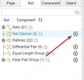
Net Class
The network class is generally used when the same type of network needs to set the design rules together.
Right -click the mouse under the network branch -new classification or click a new small icon
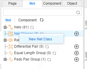
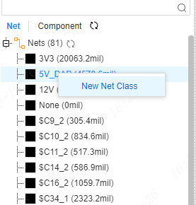
Or, right -click the "network" list on the "network" list above to create the "network".
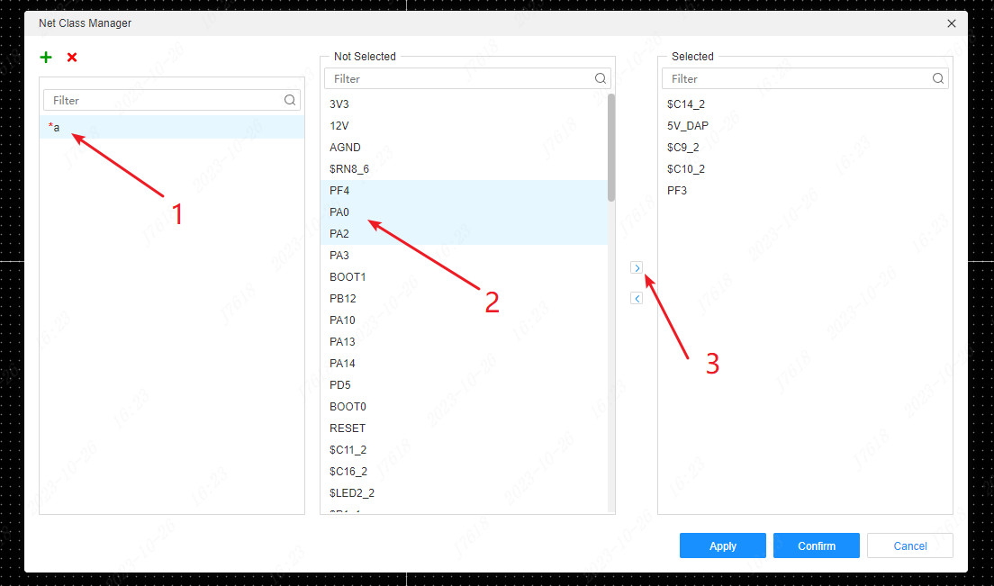
Set the name in the network pop -up window, and set the network.
The network name that has been added to the network will be displayed in the dialog box 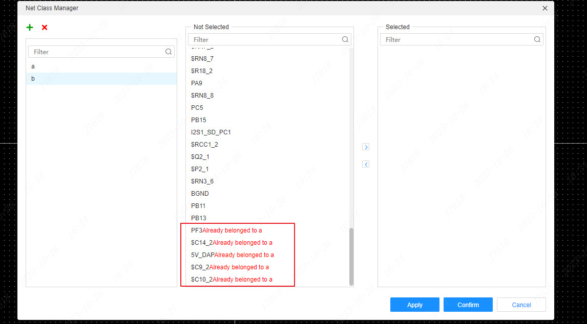
After the creation is completed, refresh the left network class, and you can see the new network category.
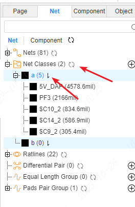
Click the sorting button to sort the network in the network class to facilitate viewing the network according to the network class.Click to sort according to the network name and network length.
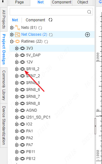
Ratlines
When wiring, hiding other flying wires that do not need wiring for the time being, which will help reduce interference and focus on the current network wiring.
You can hide the flying line on the left online tree
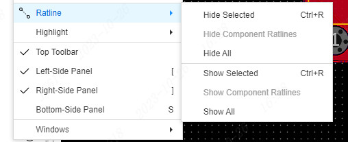
You can also select the wire after selecting the wire, and the hidden flying wire at the top view menu
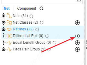
Differential pair
When the difference is required, the differential pair needs to be created first and the rules are set.
Click the new icon of the differential pair to create a new differential pair.
Set the name of the differential pair, add the positive and negative network after adding a positive and negative network
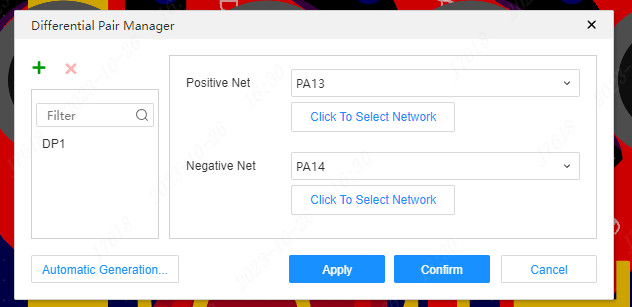
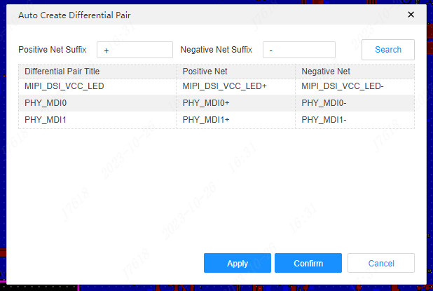
You can also use automatic generating differential pairs, which will match the same prefix according to the network name, but the suffix is different.
Equal length group
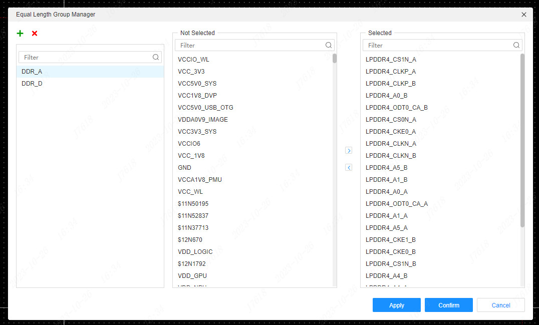
When the wiring of long -controlled control is required, the long network group can be set to compare the network length between the two or more networks, and it is convenient to set the network rules for the entire network group in the design rules.
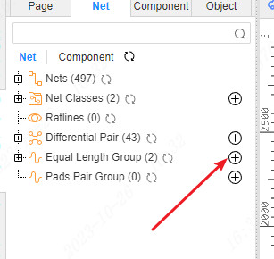
Similar to the new network class before, click the new button to create.
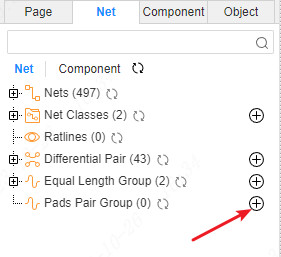
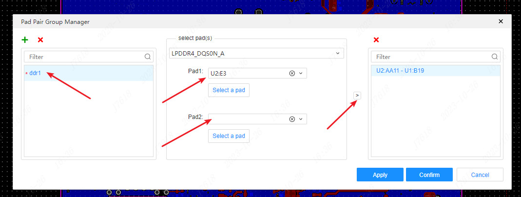
Pad pair group
Creating a pad to the group can be very convenient for differential control to the length. You can intuitively view the length of the wire network between the two pads, which is conducive to the equal adjustment.