Import EasyEDA Standard Edition
At present, EasyEDA only supports importing and importing from the standard version of the project, and does not support the professional version to export the standard version format.
Notice:
- **Due to the inconsistency of the format and graphic element design, there may be some differences after the graphic element is imported, please check carefully. For specific differences, please refer to the help documentation. **
- **EasyEDA is not responsible for any losses caused by format conversion differences, if you do not agree, please do not import. **
Download file to import
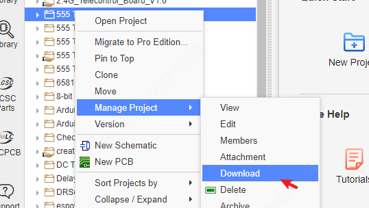
- Download the standard version of the project You can right-click in the project list of the standard version editor, and download the project. The workspace page will be opened, and a compressed footprint will be automatically downloaded.
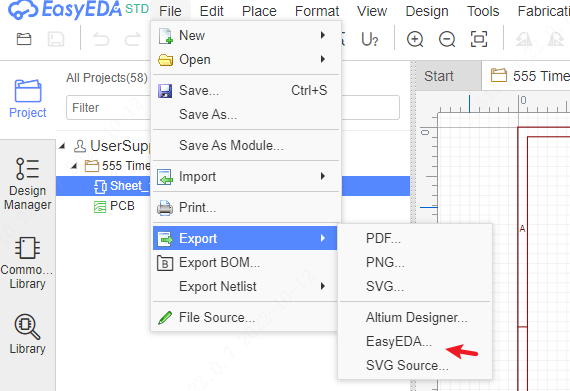
or after opened the document, export the EasyEDA file format, export schematic and PCB, and then compress as a zip file.
- If you download the project, you need to unzip the zip file to get the inner project zip file, and import it.
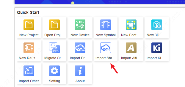
- You can also import the EasyEDA format json file not the zip file
Note: If there is a PCB, please be sure to compress the schematic and PCB together and import. Otherwise, importing the schematic separately requires all components to be re-bound and footprintd.
Migration to import
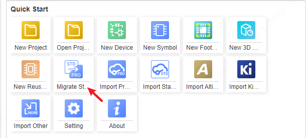
Directly on the Professional Edition start page, use the migration function to import.
Open the Standard Edition editor in the browser and log in. If you do not log in, you will not be able to get the standard version of the data.
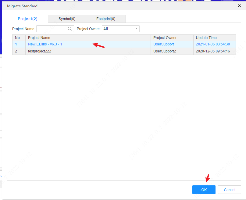
Open the professional version editor in the browser, on the start page, click "Migrate Standard Edition"
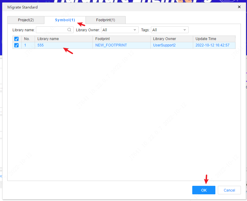
- Select the project or library to be migrated and import it.
If it is necessary to import symbols and device libraries at the same time, when using migration, only select symbols for migration, and the corresponding device library, symbol library, and import symbol binding footprint will be automatically created according to the symbol library, and automatically associated with the device.
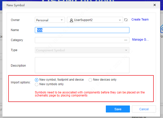
If only the footprint library is imported, the device library will not be automatically created, only the footprint library will be imported separately.
common problem
common problem
Please check carefully for other possible differences. If you find a large difference, please contact us to see if it can be optimized or repaired.
The difference before and after format conversion is as follows:
Schematic / component library:
| Elements/Layers | After Import | Notes |
|---|---|---|
| Bus/bus branch | Import is not supported | The design of the bus and bus branch of the professional version is different from that of the standard version, and cannot be directly imported and used |
| Text | Import as normal text | The professional version does not support comments at the moment. If the corresponding font is not installed in the operating system, the default font will be used after the text is imported, because the font of the text may have a slight offset in different positions; save the AD file as In ASCII, Chinese characters may be garbled, and the garbled characters will be automatically converted to underscores after import |
| Voltage Probe | Import as Network Logo | Professional version does not support voltage probe primitives |
| Non-connected logos | Free non-connected logos are not imported | Professional version non-connected logos can only be placed on pins, so free non-connected logos are not imported |
| Pins | The free pins of the schematic diagram are not imported | The professional version does not support placing pins separately in the schematic diagram |
| Bezier curve/ellipse/free drawing | Import as polyline | Professional version does not support Bezier curve, Bezier curve, ellipse arc, ellipse |
| Canvas origin | The default is the lower right corner of the drawing | If there is no drawing, it will be imported according to the original canvas origin |
| Arrows | Import is not supported | Arrows are not supported in Pro version |
| Grid size | Import in proportion | The grid of the standard version is pixels, and when the grid is 5, the professional version corresponds to 0.05inch |
| Pin type | Unsupported types are converted to input types | The professional version only supports three pin electrical types |
| Hidden pins | Show after import | Professional version does not support hidden pins |
| Component footprint | After importing, the "original package" attribute will be generated | The professional version does not associate the package with the package name, but with the uuid of the package, so when importing, the original associated package name will be added as a common attribute. If the imported schematic and PCB When compressing and importing together, the package will be automatically associated |
| Component Mirroring | Will be imported as different component templates | The standard version of the component has not been recorded in the file whether it has been mirrored (flipped), so when importing the professional version, no matter whether the mirrored or not mirrored component will be imported as a different template library (in The project library at the bottom can see two devices with the same name) |
| Theme style | The default theme of the professional version is used in the import dialog box | The default theme is that the rounded rectangle is converted to a right angle, the fill color is not preserved, and the color of the primitive is not preserved, so as to switch the schematic theme, and the theme of the original file follows the original file Style, color does not change when switching themes |
PCB/Package Library:
| Elements/Layers | After Import | Notes |
|---|---|---|
| copper area | copper area will be re-laid after importing | Because the copper area logic is different, the copper area filling of the PCB will also be slightly different. For example, the heat welding generation method, the heat welding width, whether the heat welding is generated (it will give priority to avoid generating heat welding for the graphics elements with wrong DRC spacing), and flying lines may be generated |
| Text | Font changes and positions will be slightly shifted | If the corresponding font is not installed in the operating system and the corresponding font is not added in the font setting of the professional version, the default font (Arial and Arial) will be used after the text is imported, because the fonts of the text are in different positions There may be a slight offset; if it is the same font, because the font display logic is different, it cannot be completely consistent with the original file, and there will be position offset and size difference; strokes and barcodes will be converted to normal text |
| Internal electrical layer | The network of the block may change after importing | The internal electrical layer of the standard version and the professional version are implemented differently. When there are multiple internal electrical blocks, the network of the blocks may not be completely consistent. Check carefully; after importing, the internal electrical layer will rebuild the block, and the internal electrical layer block division may also be different |
| Solid Region | Go to different layers or types depending on type | Cutout type to Slot Region; Solid to Fill Region; No Solid to Prohibite Region |
| Ratlines | Flying lines appear after importing | It may be that the reconstruction of copper area after importing leads to disconnection in some places, such as no network primitives, heat welding cannot be generated due to DRC spacing, etc. |
| 3D model library | does not support import | The 3D binding design of the professional version is different from that of the standard version. The 3D library import of PCB and package binding will not be imported together in the professional version, and the 3D model library needs to be re-bound |