3D Preview
Generate a 3D preview of the designed board
Steps:
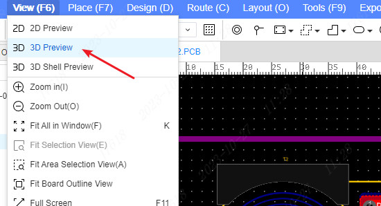
Top Menu - View - 3D Preview
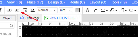
Top Toolbar - Click on 3D Preview icon
Turn on the 3D previewed PCB, the 3D previewed PCB is similar to the produced PCBA.
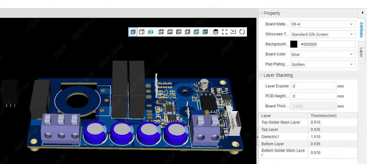
In the right panel of the 3D interface, you can modify the color of the current board to simulate the generated PCB and 3D model. If the components of the PCB are not bound to the 3D model of the component, you need to bind the 3D library first in the PCB: Top Menu - Tools - 3D Model Manager.
Property description:
Board Material:The material of the PCB plate base plate, including glass fiber board, FPC, aluminum substrate, copper -based plate, ceramic plate, and iron fluorine.
Silkscreen Technology:It is divided into standard silk screen and colorful silk screen. colorful silk screen are the unique process of JLC, which can produce color PCBs.
Background Color: The background color setting of the preview interface
Board Color: The color setting of the PCB board. Seven color settings are supported.
Pad Plating Color: Color preview of PCB pad spraying, gold or silver
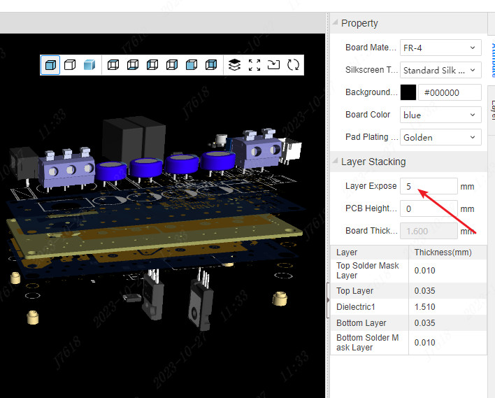
Layer Expose: The spacing of each layer, the settings can be used to view the graphics of each layer separately.
PCB height from the bottom of the casing: Supports setting the height of the PCB board to the bottom of the casing and previewing the position.
Board thickness/layer thickness information: This is displayed according to the layer thickness set by the layer stack in the layer manager of the PCB. If you need to modify it, please modify it in the Layer Manager: Top Menu - Tools - Layer Manager - Layer Stack.
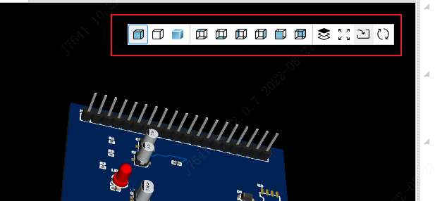
Preview toolbar:
The preview toolbar supports a variety of functions. When the mouse is suspended on the icon, the corresponding function name can be prompted.support:
- Normal view, contour view, Gerber view, contour view is only used for 3D shells.
- The top surface, bottom surface, left side, right side, front, back, back
- Explosion: 3D shell preview use
- Adapt to all: The current preview adapts to the view area
- Import change: Introduction to PCB changes
- Refresh: Return to the default angle
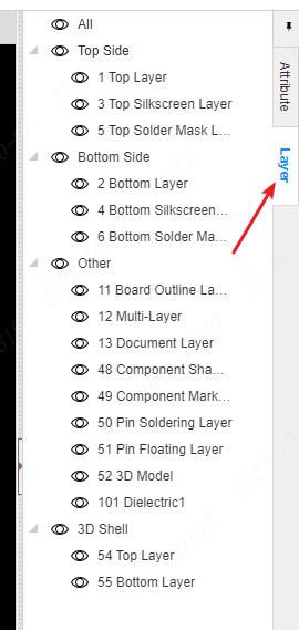
Layer switching:
Support to hide some unwanted layers on the right side. The 3D shell can also be hidden here.
Top toolbar:
The top toolbar supports exporting pictures and 3D models.
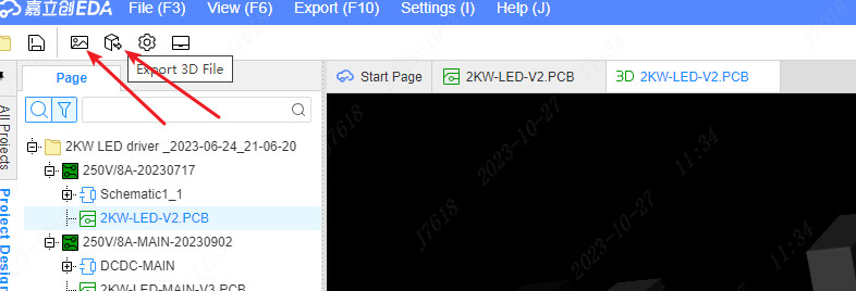
The default width of the exported image is 2160, which is exported according to the current canvas state, and the background is transparent. 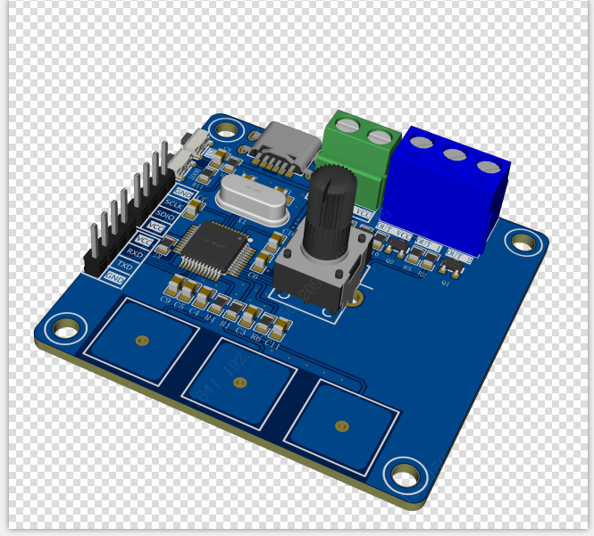
Notice:
- The preview of this 3D function is a preview of the simulation image of the generated file, which cannot be used as a real object. Please refer to the production results for specific results.
- If you need a 3D preview of a separate window, please use the "3D Shell Preview" function.