Symbol Settings
Steps:
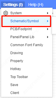
- Top Menu - Settings - Schematic/Symbol
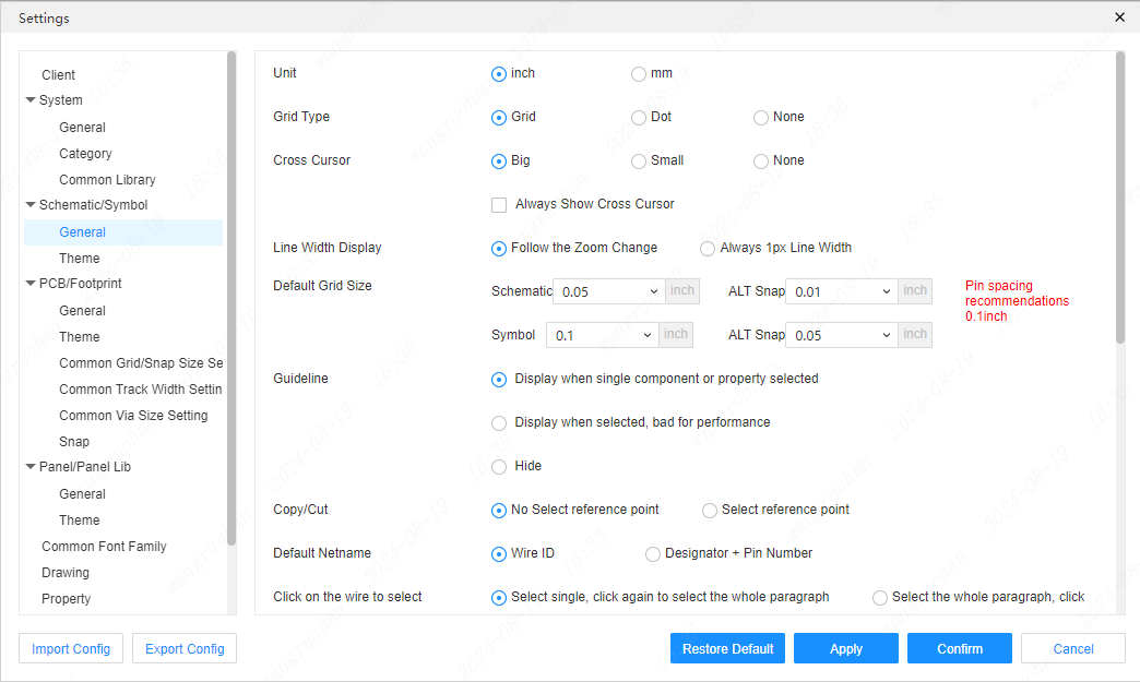
grid type
Set the default canvas! image-20201219153627002 There are only three grid types, namely dot, grid, and none.


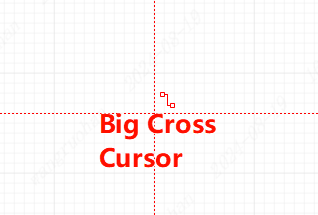
crosshair


line width display
Sets the size of the line width of the overall device line width.
The line effect that follows zoom changes will become thicker.
Default grid size
Modify the schematic page and default grid size to match the drawing page.
indicator line
Modifying the property indication of the schematic device can be modified into the following three.
- Show when selecting a single device and selecting an attribute: Display the indicator line when a single device or attribute is selected.
- Show when selected: Display the indicator line when the attribute is single-selected.
- DO NOT DISPLAY: Do not display the indicator line.
Move symbol, wire follow mode
- Follow by default, press and hold AIt to disconnect before the movement starts: When the symbol moves, the wire will move with the symbol. Press and hold the AIt key to move the symbol, and the wire will not move with the symbol.
- No follow by default, press and hold AIt to keep connected before moving: When moving the symbol, the wire will not move with the device, you need to hold down the AIt key to move the wire with the device.
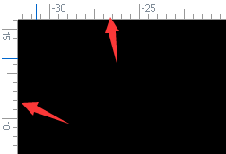
show symbol ruler
Automatically assign tags when placing or pasting devices
Tag numbers are automatically assigned when components are pasted or placed.
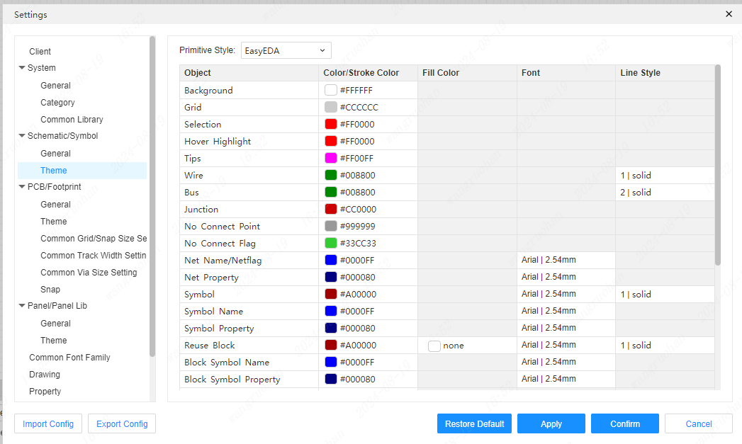
Schematic theme settings
Here you can modify the background color of the schematic page or the color of the text, the default font, and the default line type.