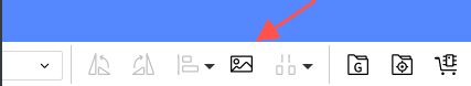
Top Panel - Toolbar
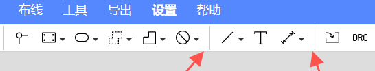
The toolbar in the top panel of the PCB is a shortcut bar for some commonly used tools

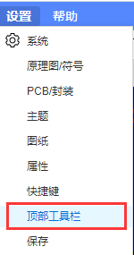
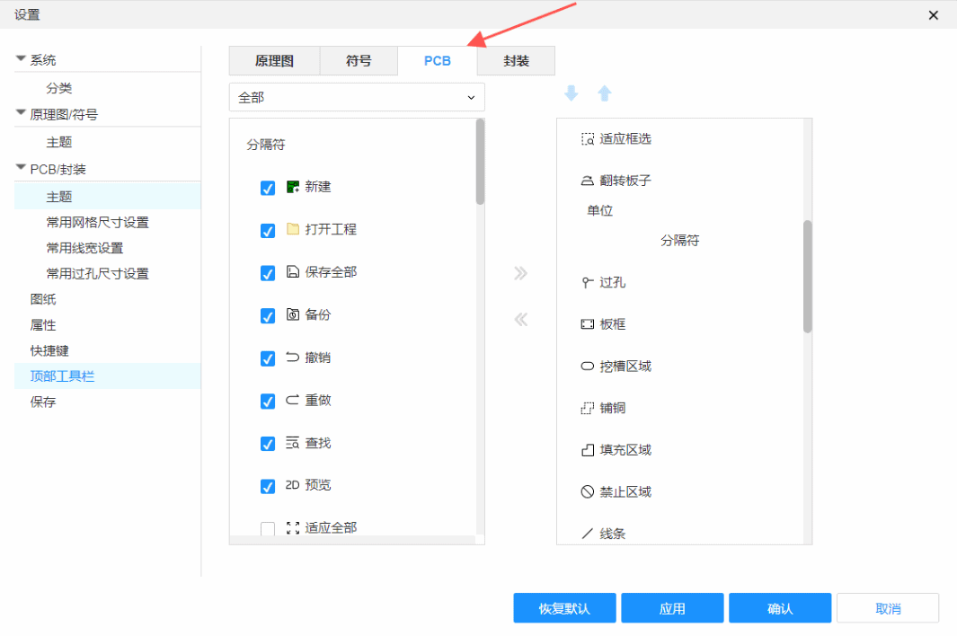
Set up the shortcut bar
- Top Menu - Settings - Top Toolbar
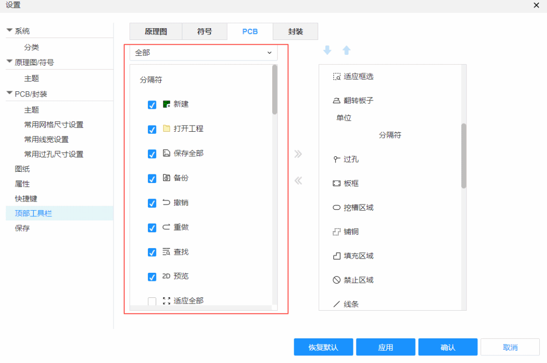
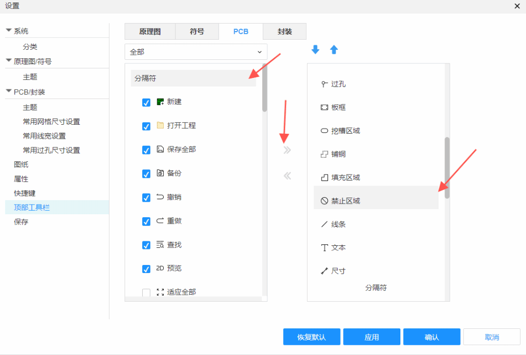
In this pop-up window, you can set the top toolbar settings for schematics, symbols, PCBs, and footprints. The red box in the figure refers to the top menu of each interface.
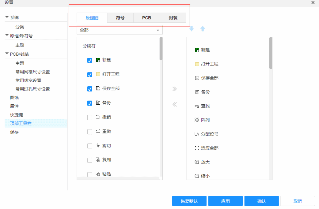
Click the checkbox to see a categorized display of tools
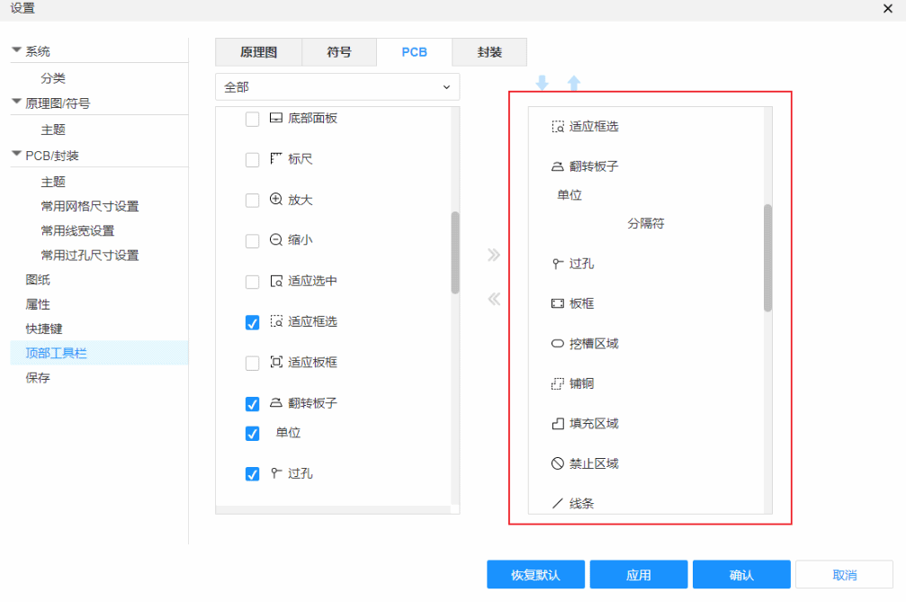
Customize the top toolbar
Click Settings on the top toolbar of the corresponding interface
On the left side of the pop-up window are some shortcut tools that can be added to the top toolbar
The right side of the pop-up window is the shortcut tool that has been set in the top toolbar
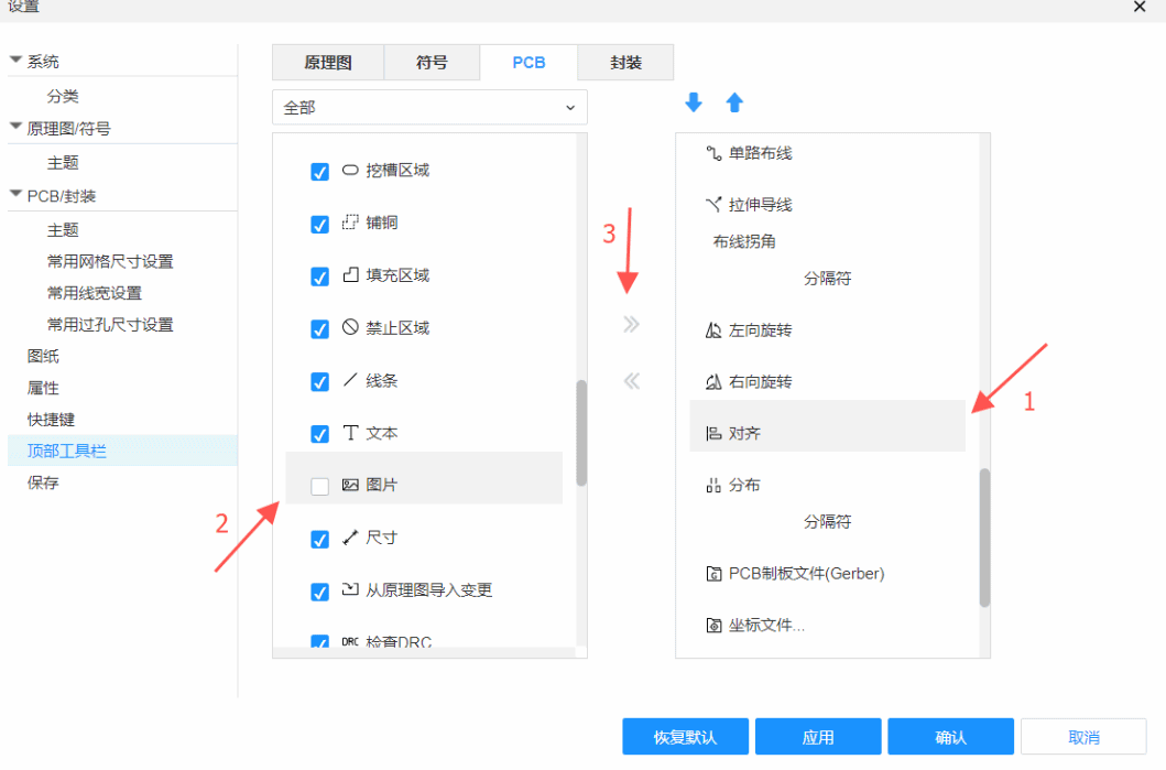
First select the location on the right to add the shortcut function, and then select the shortcut function to be added to the left on the left, click the arrow in the middle or tick the check box, and click OK to add it to the selected location. !
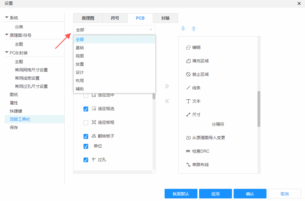
Classification
In the top toolbar, each function shortcut will have a separator as a classification plan and this separator can be modified in the settings.

The method of adding a separator is similar to the operation of adding a shortcut function. First, select the place to be separated on the right, select the separator from the left, and click the arrow in the middle to add the separator to the top toolbar, and click Save. Save and apply the current settings to the PCB interface.
As you can see, the shortcut functions of the top toolbar are separated