Schematic Settings
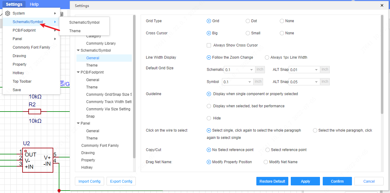
Operation steps: Top Menu - Settings - Schematic/Symbol
General
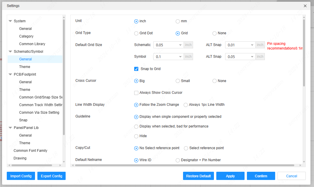
Grid Type: Set the default canvas. You can set Dot, Grid, None.
Cross Cursor: Set the cursor size of the schematic editor;
Line width display: Set the line width of the overall device line width;
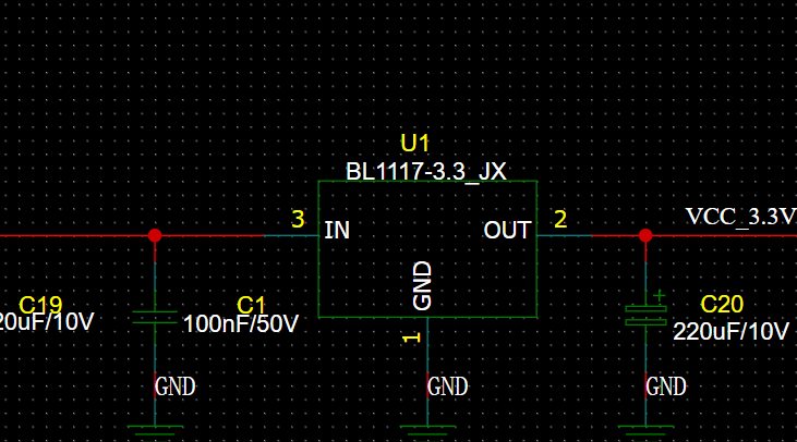
The line effect that follows zoom changes will become thicker.
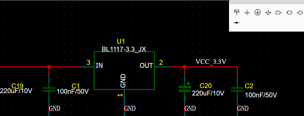
Default grid size: Set the grid size for opening or creating a schematic, which cannot be changed;
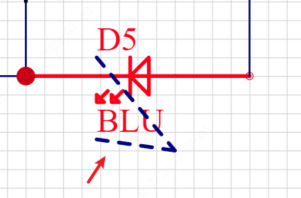
Guideline: Whether to display the indicator line between the component origin and component properties according to the setting.
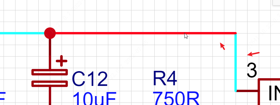
Click on the wire to select:According to your own usage habits, you can switch the selection range when you click the wire, select a single segment or select the entire segment.
Copy/Cut: Whether to select a reference point when copying/cutting.
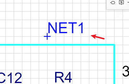
Drag Net Name: How to handle when dragging a wire's net name off the wire.
- Adjust the attribute position: only move the position of the attribute name, without affecting the net name of the wire. The behavior before the professional version is similar to the behavior of the network tabs of PADS and Orcad.
- Modify net name: When the net name leaves the wire, the wire's net name will be cleared, similar to the Altium and Standard version's net label behavior.
Drag symbol, wire's following way: Set whether the wire moves with the component.
Other:
- Symbol Editor Display Scale Ruler
- Annotate designator automatically while placing or paste device(paste doesn't support multipart/subpart)
- Highlight entire network when hovering wire
- Adjust properties location automatically when components are rotated
Components placement for per page: At present, placing too many devices in the schematic diagram will cause lag, so the number detection is added. It is recommended to place less than 100 components on one page, and place other devices by creating paging.
Theme
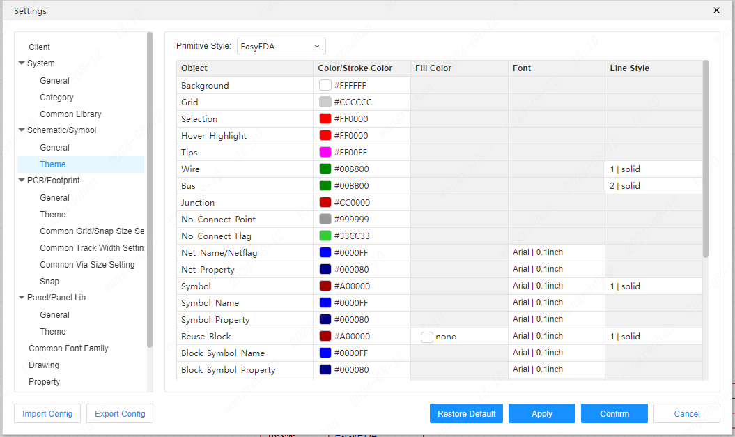
Schematic theme settings
Here you can modify the background color of the schematic page or the color modification of the text.
