Differential Pair Routing
Differential pair routing
Differential pair routing is a technique that requires the creation of a transmission system on a printed circuit board that favors the balance of differential signals (equal and inverted signals). The differential line is generally connected to the external differential signal system. The differential signal system uses twisted pairs for signal transmission. One signal line in the twisted pair transmits the original signal, and the other transmits the signal with the opposite phase of the original signal. Differential signal is a method used to solve the problem that there is no good reference ground connection between the signal source and the load, and it has an inherent inhibitory effect on the interference of electronic products. Another advantage of differential signaling is that it reduces the electromagnetic interference (EMI) generated by the signal lines.
Set differential trace steps:
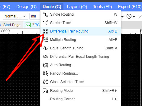
- Top Menu - Routing - Differential Pair Routing.
Create differential pair network class
Before performing differential pair wiring, you need to set up the differential pair network class.
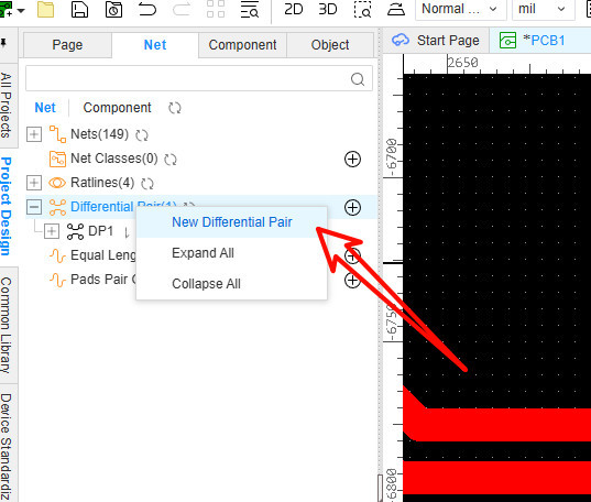
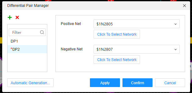
- You can right-click on the differential pair category on the left network tab and create a new differential pair.
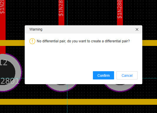
- You can also directly click the wiring menu - differential pair wiring. After clicking the pad, if it is detected that no differential pair has been established, a pop-up window will prompt you to create a differential pair.
- It is very convenient to create differential pairs
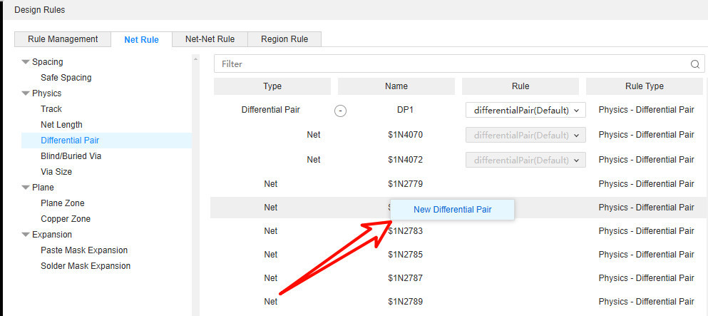
- Design Rules-Net Rule-DifferentialPair.Right-click to create it
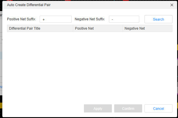
Differential pairs can be automatically generated, and the query generation is performed according to the positive and negative signs of the network name:
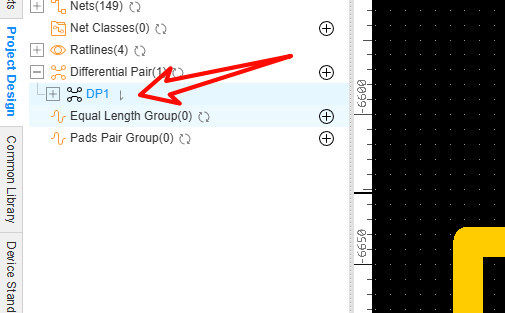
After creating the differential pair, you can see it on the left network tab. And you can see the total wire length of the network.
Create differential pair rule
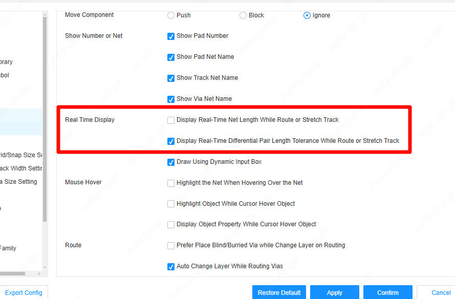
When the rules are set, you can click the differential pair routing menu to perform differential pair routing, and you can also view the wiring length and difference in real time during the routing process.
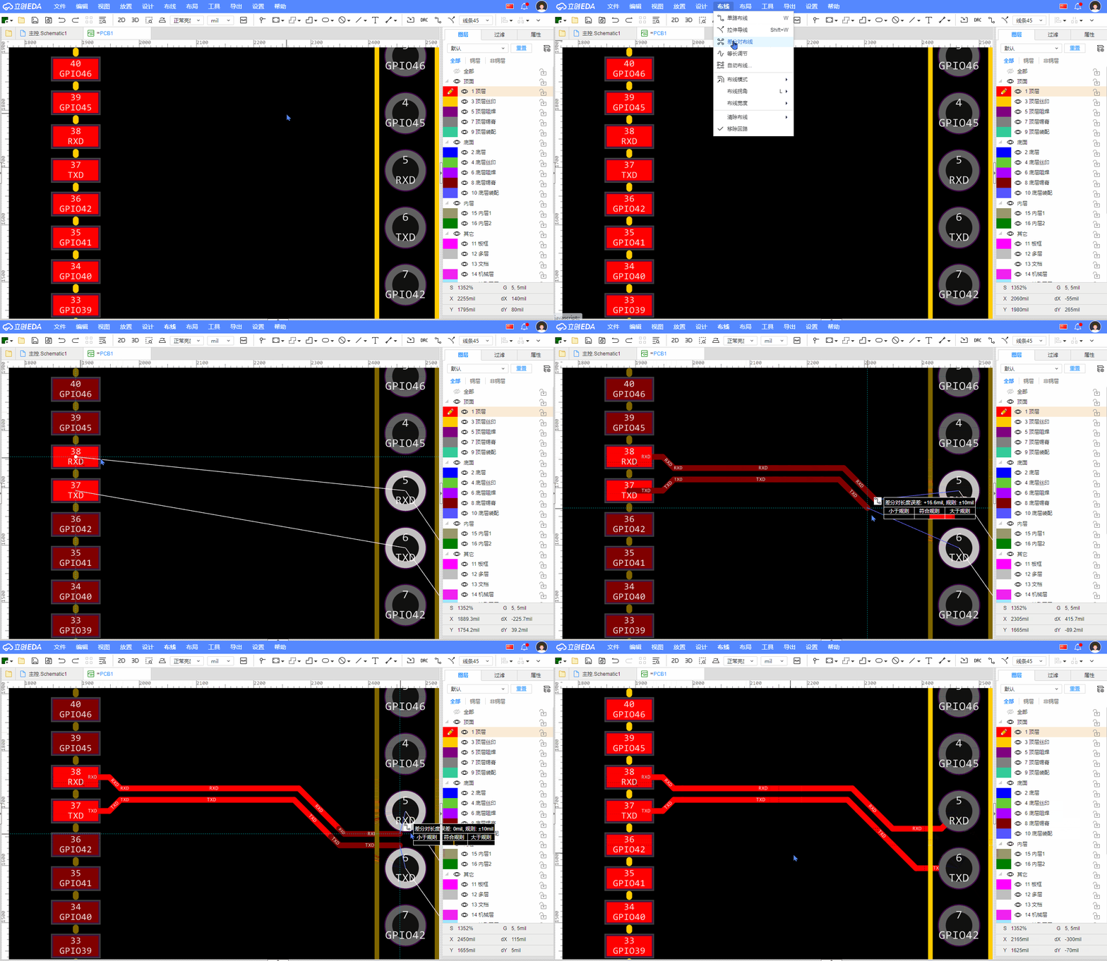
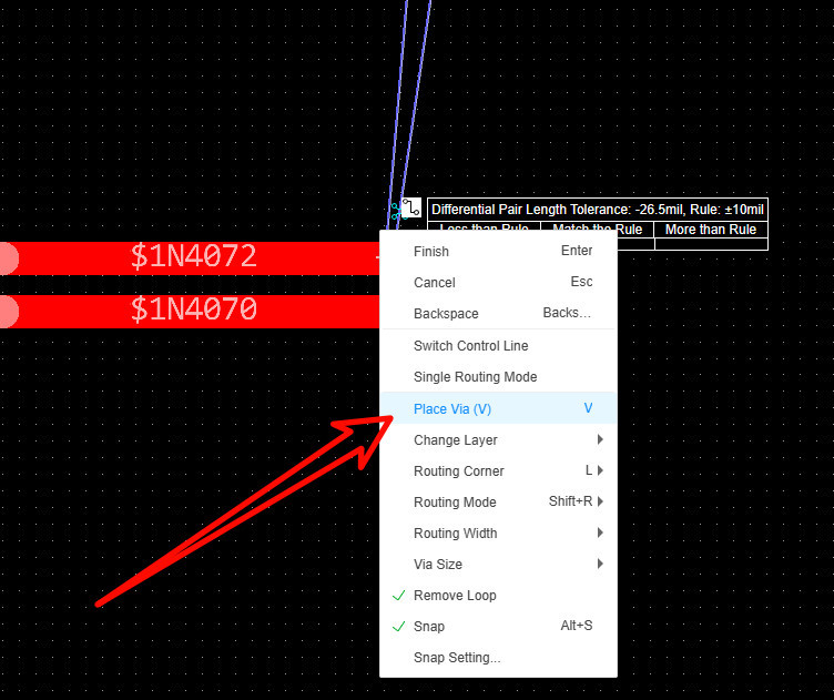
In the process of drawing, you can switch the path by pressing the space bar, and use the shortcut key or double-click or right-click menu to cut layers.
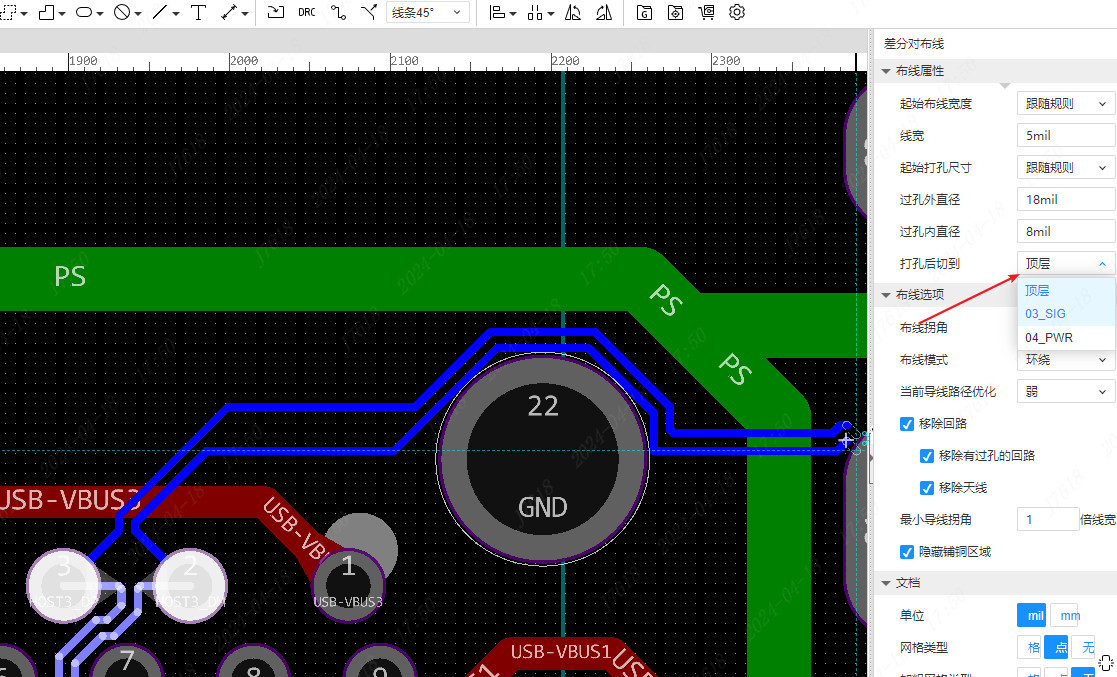
If you want to cut to the specified layer after punching through the right click menu or double click, you can modify it through the right property panel
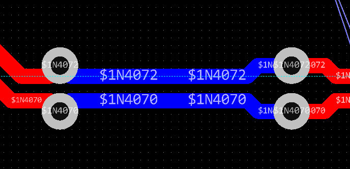
When using the shortcut key to cut the layer, or when adding vias, you can toggle the fan-out direction of the wire and vias by pressing the space bar, as shown in the following two ways:
In the wiring process, the endpoint of the control line will display a mark. If you need to switch, you can switch the control line through the right click menu
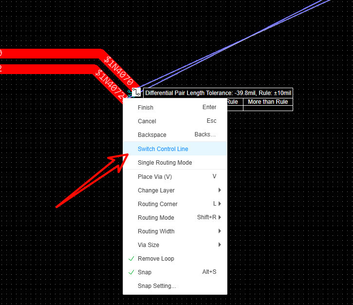
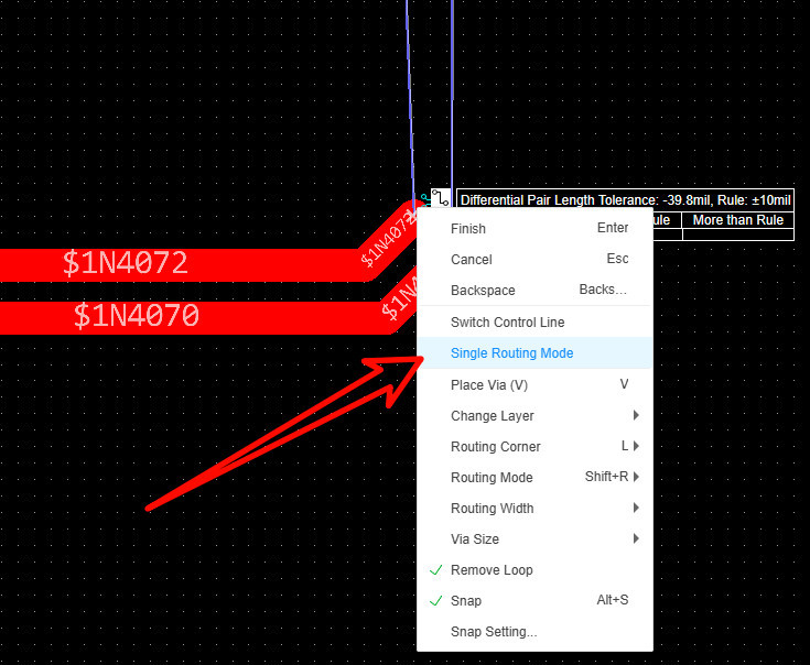
In the process of differential routing, you can temporarily switch to single routing mode through the right click menu. After wiring a network, you can automatically switch to another network, and click again to switch back to differential routing mode.
During the routing process, the upper-right corner of the cursor will indicate the routing error and whether it conforms to the rules.
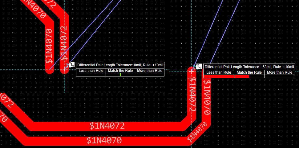
If there is no display, you can enable real-time display in Settings - PCB Settings - General.
