Board Outline
Before starting the PCB design, you first need to create a frame for the board. The board frame can be created by direct drawing and by importing DXF.
illustrate:
- Only one plate frame can be placed in a plate frame, more than one plate frame will be turned into a grooved area
draw directly
- Top Menu Place - Board Frame
- The top toolbar board frame enters the drawing mode, providing three ways to draw rectangle, circle and polygon
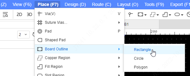
The drawing methods of the board frame, copper area, filling area, slotting area and forbidden area are exactly the same.
Import DXF
You can switch to a board frame through any type of contour object. If the line is not closed, it will prompt to automatically close the contour. This function is mostly used to convert the imported lines to the desired type (plate frame, cutout area, forbidden area, etc.) after importing DXF.
- Click on the top menu File - Import - DXF Select the DXF file you want to import
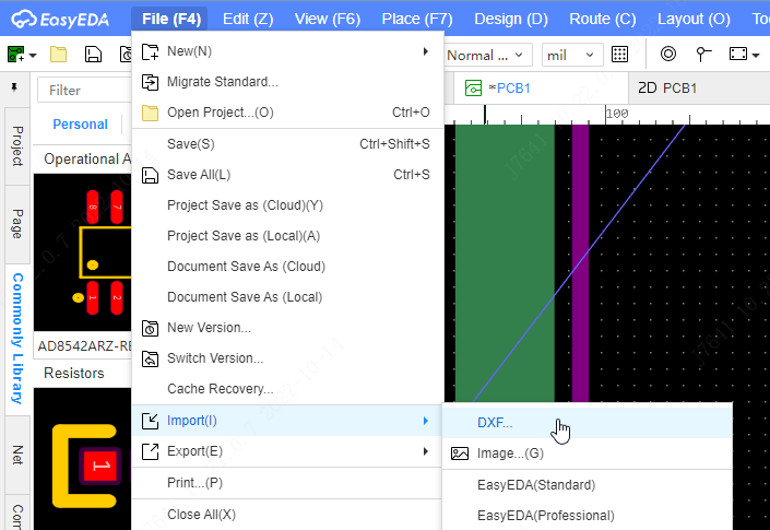
the more import dxf information please refer at Import DXF section.
Notice:
The plate frame and grooving area must be closed. If the line you select is not closed, you need to select multiple lines and merge them into a whole through the right-click menu Merge as closed object, and then convert the plate frame
The non-closed lines of the board frame layer will also be exported as the board frame layer, which does not affect you to draw the board frame with lines.
add rounded corners
The method of drawing a rounded rectangle border in the professional version is different from that in the standard version. It is split into another function. The specific operation steps are as follows:
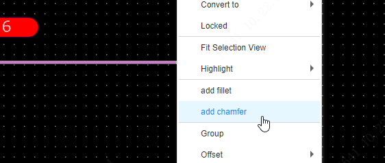
Select the board frame, the board frame needs to be a complete closed loop to generate rounded corners - right mouse button - add rounded corners
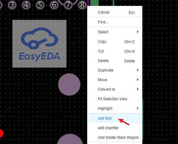
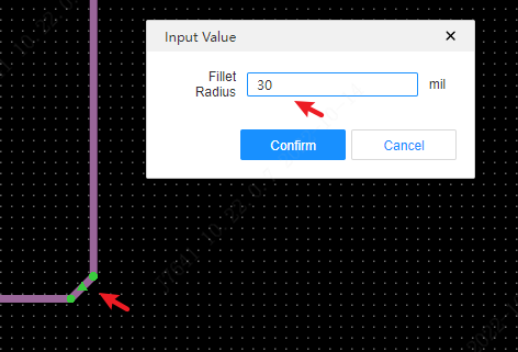
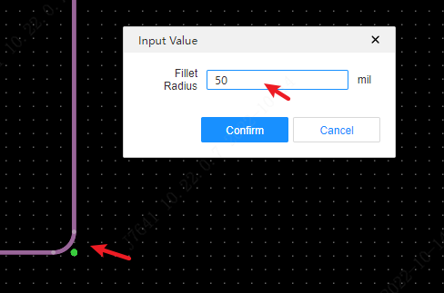
Enter the width of the rounded corners in the pop-up window - click OK to generate rounded corners for the board frame
Add Chamfer
The operation steps are the same as adding rounded corners, and will not be explained here.
