V1.9.x Update Notes
Note
- This version has a new EasyEDA theme for shortcuts, and the shortcuts for many functions have been modified, so please pay attention to the new shortcuts.
- This version supports to hide the separate entry of symbol library in the settings, to make sure the interaction of library building is basically the same as the standard version.
Schematic
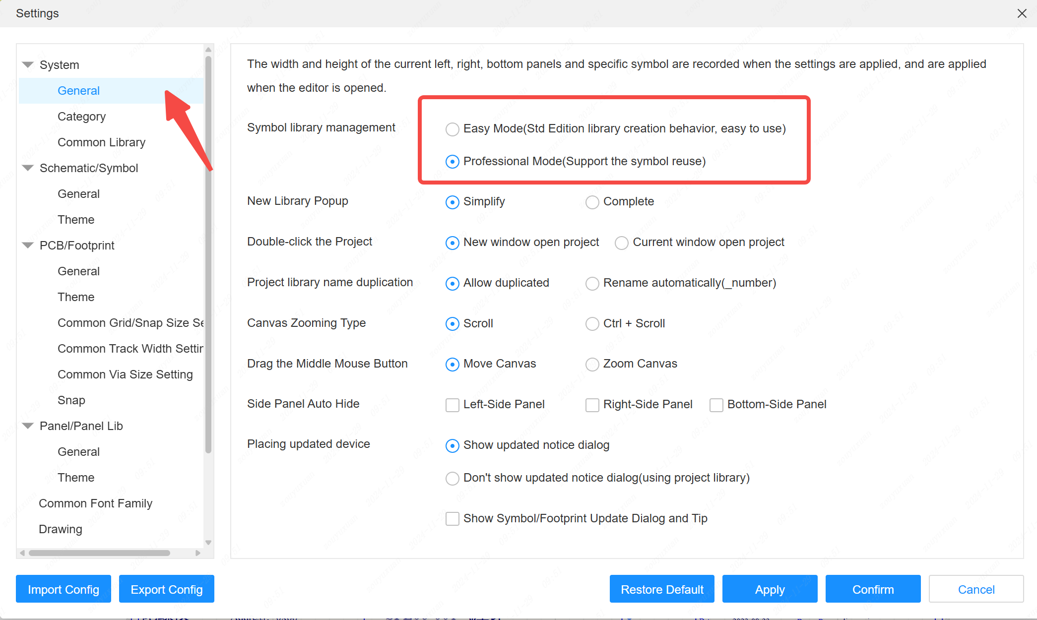
Symbol library manager supports easy mode and professional mode switching.
Entry: Settings - System - General - Symbol Database Manager. Simple mode hides the separate symbol editing portal, consolidating and simplifying the symbol and device creation and editing process!
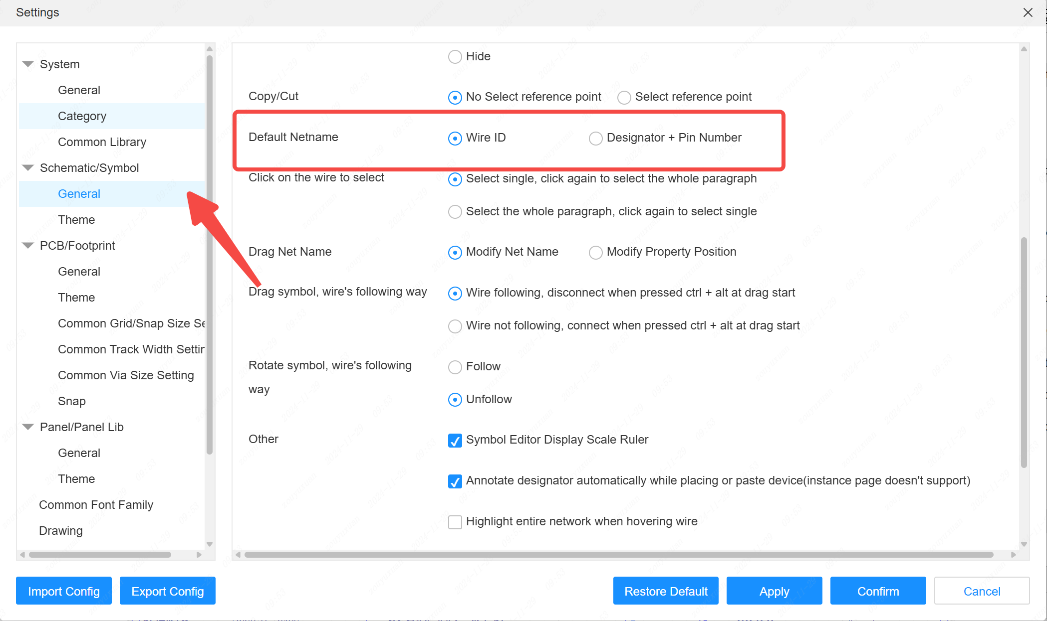
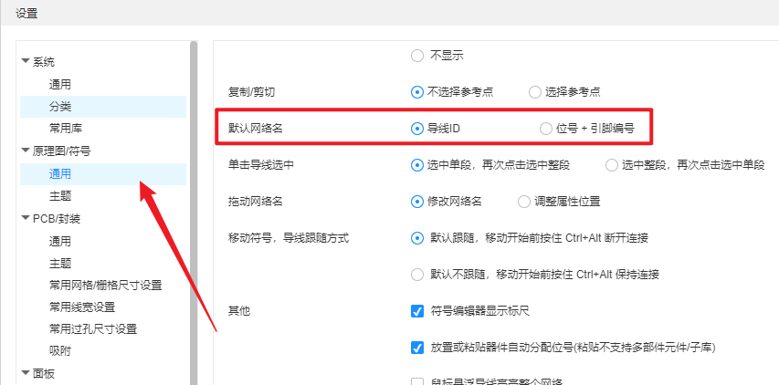
Support setting the default network name rule for schematic wires, support bit number + pin number to be the network name.
Entry: Settings - Schematic - General - Default Network Name
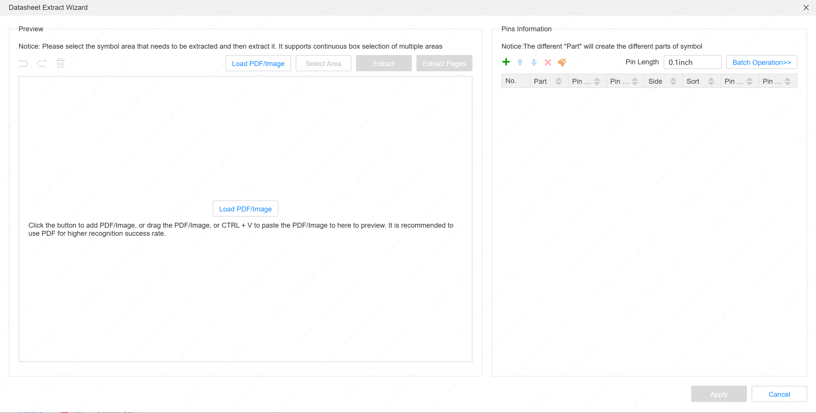
The symbol library supports the specification extraction wizard.
Entry: Symbol Library - Tools - Specification Extraction Wizard.
How to use: Open the Specification Component Pin Definition page, take a screenshot, paste it in the Specification Extraction Wizard dialog box, it will perform OCR to identify the pin name and pin number, and then create the Symbol Library in the next step.
Support for automatically clearing wire names when copying and pasting wires that do not show a network name
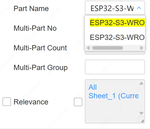
Support part switching for multi-part components.
Entry: Multi-Part Component - Properties Panel - Part Name Properties Click to Switch
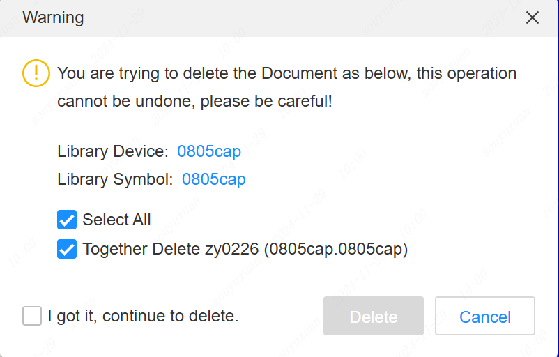
- When deleting device libraries, support for choosing whether or not to delete associated symbols and packages at the same time
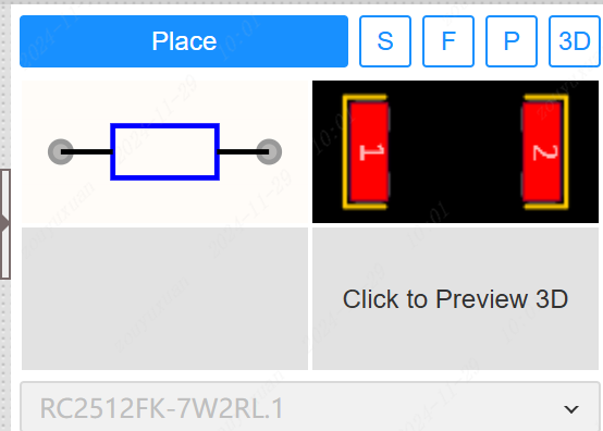
- Support for placing drawing devices in the bottom library
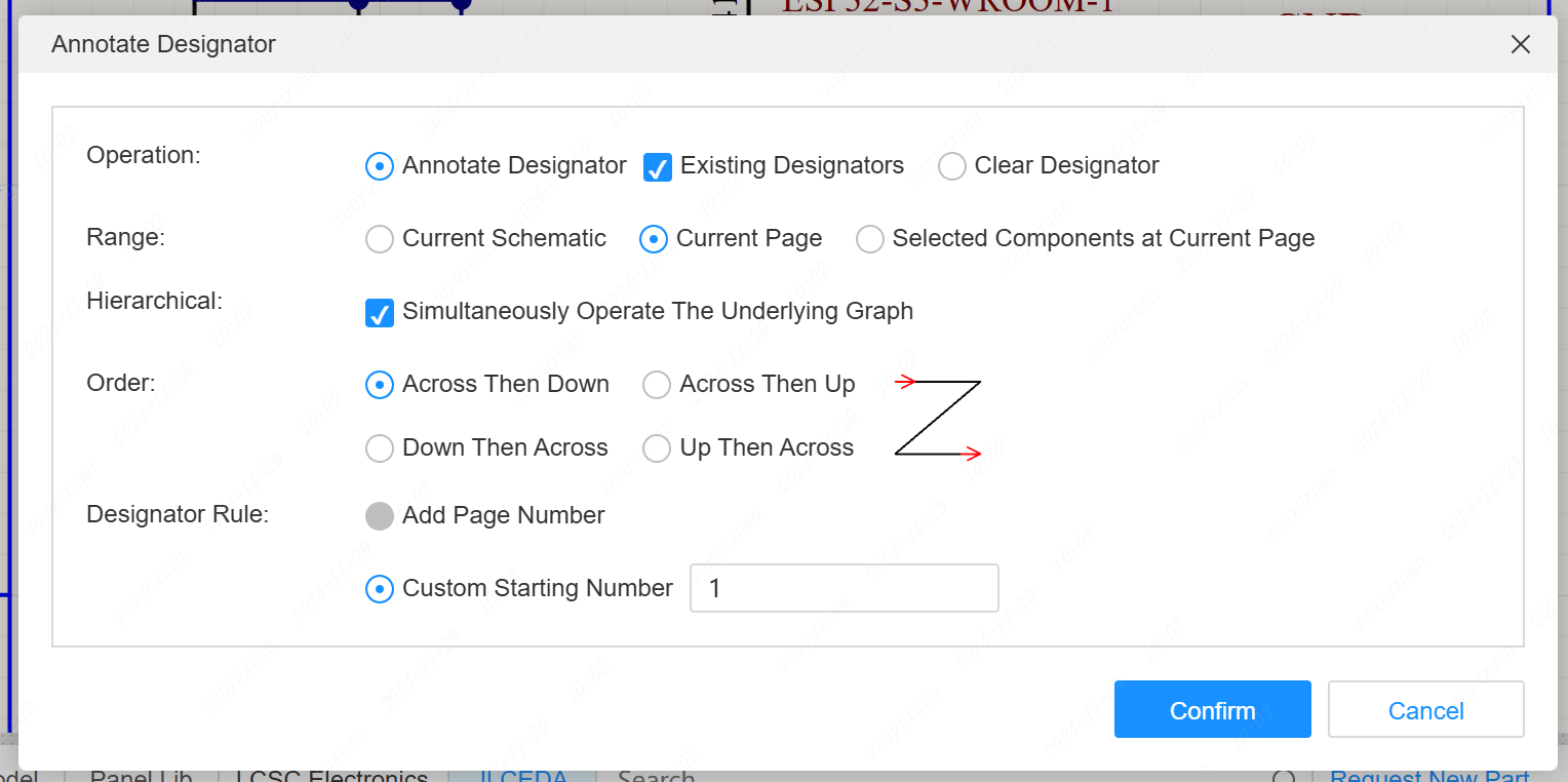
- Support for more directional sequential assignment of bit numbers
- Optimize arrow keys to move artifacts
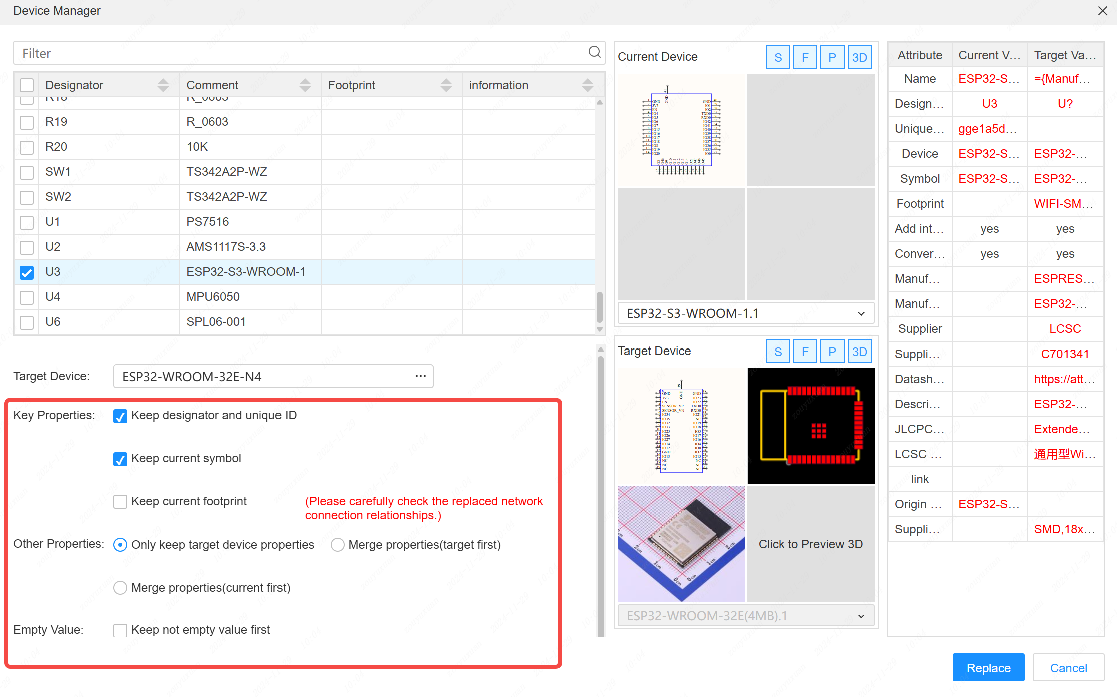
- Optimize device replacement logic in Device Manager. Support for replacing symbols and packages and 3D models
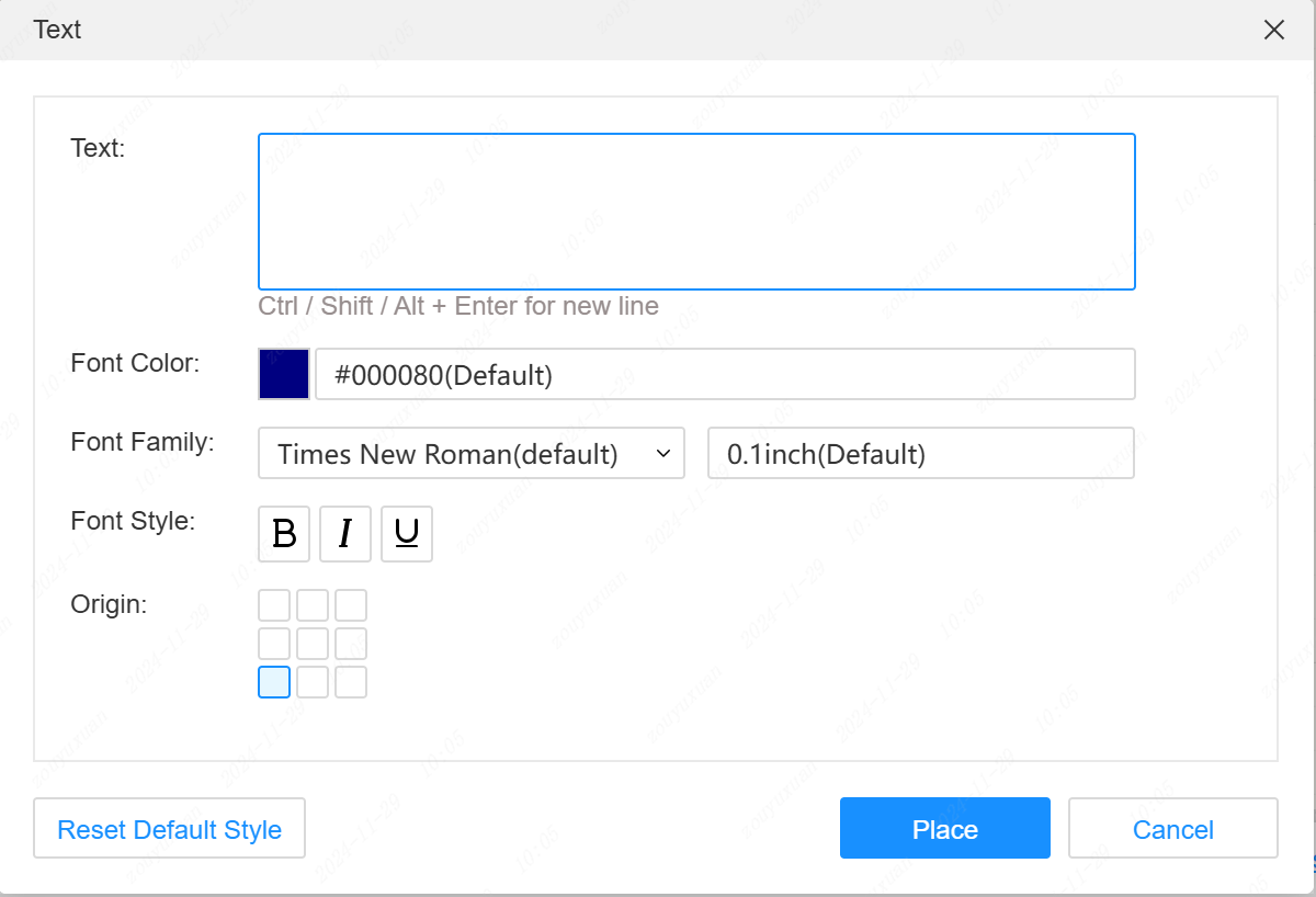
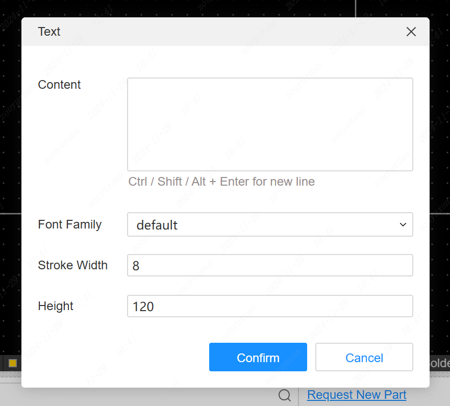
- Place text support to set more styles
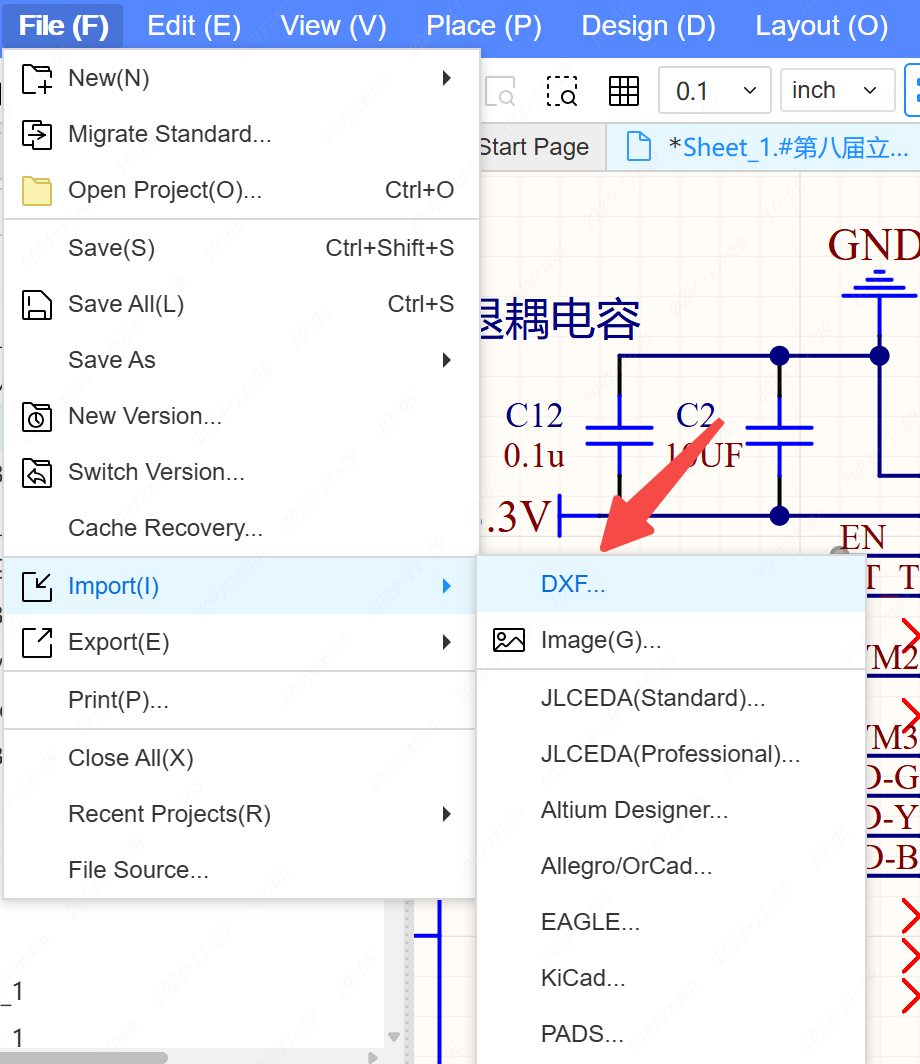
- Schematic and symbol libraries support importing DXF
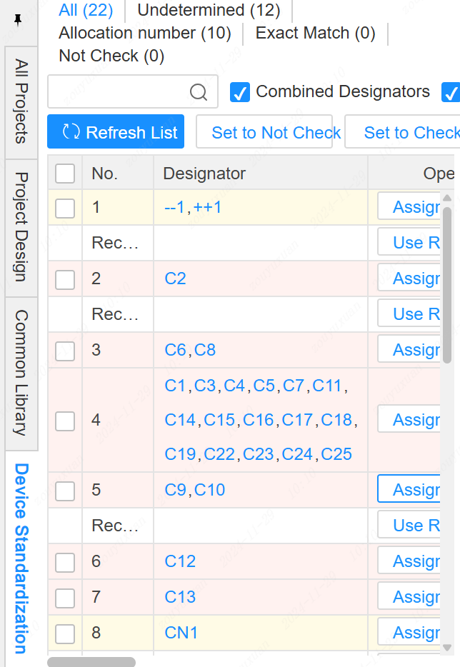
Support device standardization settings.
Entry: device standardization tab on the left side. support to assign the device without LCSC number.
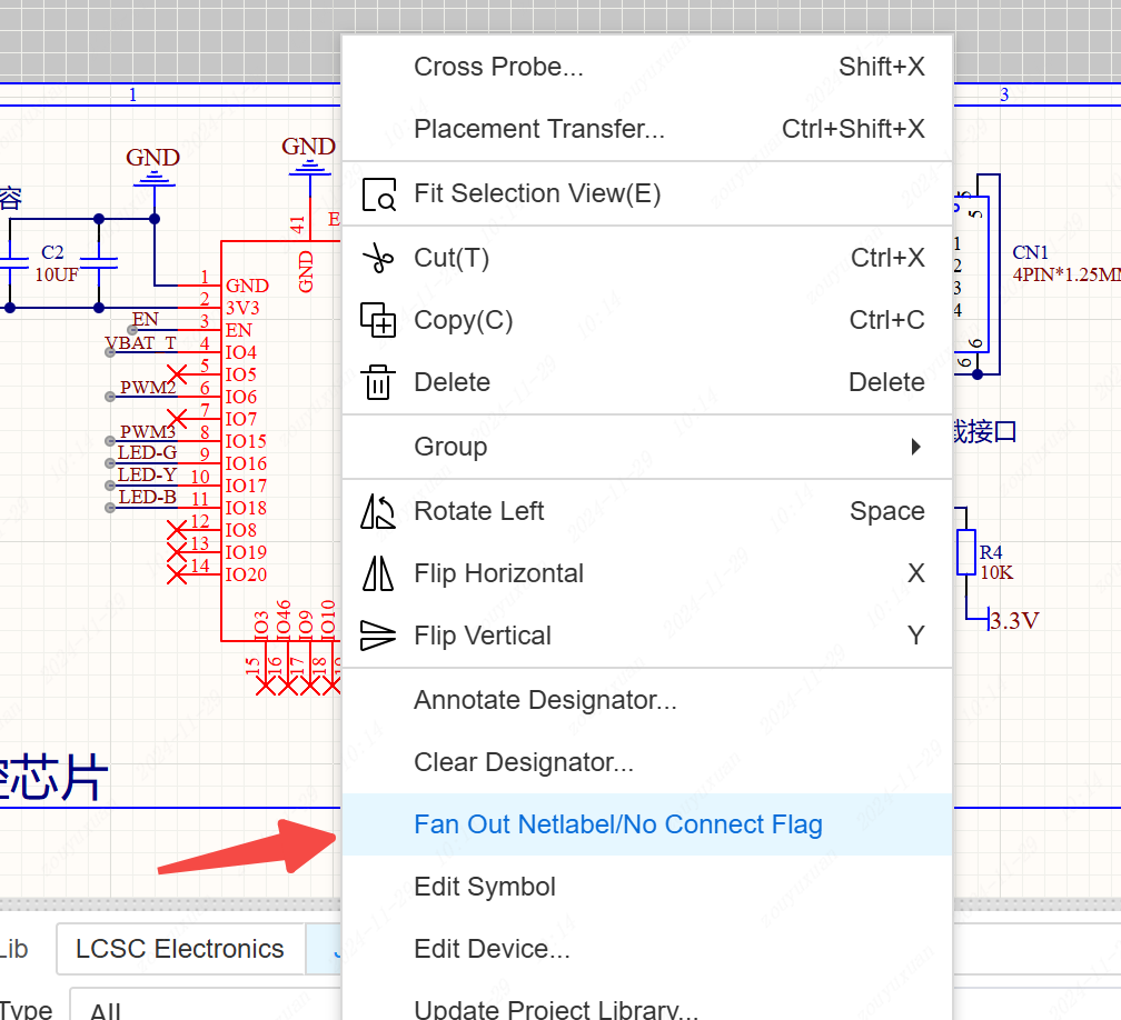
Component right-click menu supports wire fanout.
Entry : Component right-click menu - fanout network label/non-connected logo
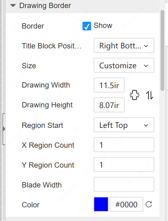
- The properties panel on the right side of the drawing supports direct resizing of the drawing and toggling of the drawing size
- Optimize wire dragging logic and performance
- Support automatic switching to Garrison EDA engine when searching for devices with product number beginning with C9900.
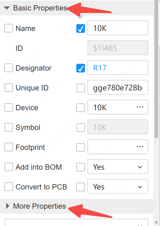
- Add “Key Properties” and “More Properties” grouping collapsed in the right property panel of the component.
The right property panel of the component is now collapsed into “Key Properties” and “More Properties” groups.
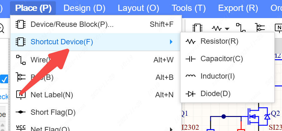
- The top toolbar and placement menu support shortcut device placement, resistor capacitor inductor
PCB
- Supports smaller height adjustment for isometric wiring.
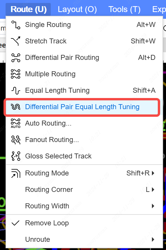
- Supports differential pair isometric routing. Entry: Wiring - Differential Pair Equal Length Wiring
- Optimize Gerber's pad representation so that board makers can recognize pads properly
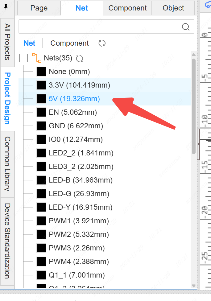
- Support filtering and picking up empty network tuples, and the left side tree supports viewing empty networks.
- 3D outline view adjusted to only outline 3D shells
- Support panning the canvas to the center according to the current mouse position, shortcut key SHIFT+HOME.
- Support switching between inner layer 3 and inner layer 4 with the number keys 3 and 4.
- Support to ask whether to open the layer which is not supported by the current PCB when placing or pasting the package
- Support drawing dimension elements on user-defined layer
- Optimize cancel combination, support single object move out of the combination
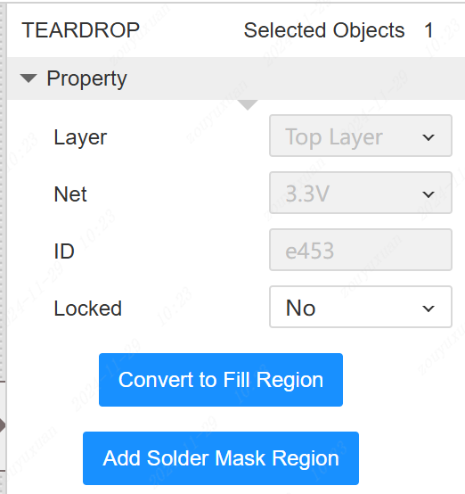
- Support property panel when teardrop is selected, support manual deletion of teardrops
- Support to delete teardrops manually
- Deleting components supports popup prompts, no longer prompts are only valid for the current PCB, reopening the PCB will prompt again

- Optimize the handling of adding perforations when wiring violates DRC.
- Added export of 3D shell related elements to DXF export.
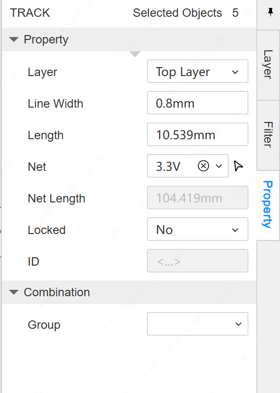
- Add network length to the property panel after selecting wires.
- Drawing of copper-laying, filled areas, and line support inherits the network of the first touched element
- Optimize real-time DRC to detect after the drawing of the graphical elements to avoid lag in the drawing process
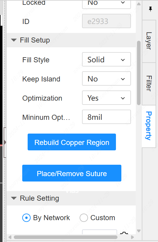
- Inner electric layer blocks support setting whether to keep the silo
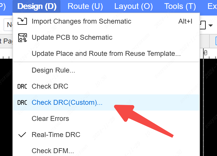
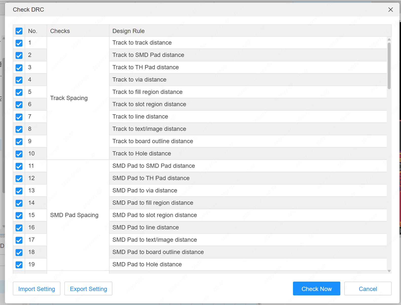
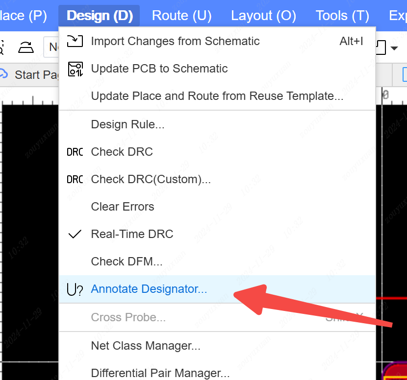
Support for customizing some of the design rules for checking.
Entry : Design - Check DRC (Custom)
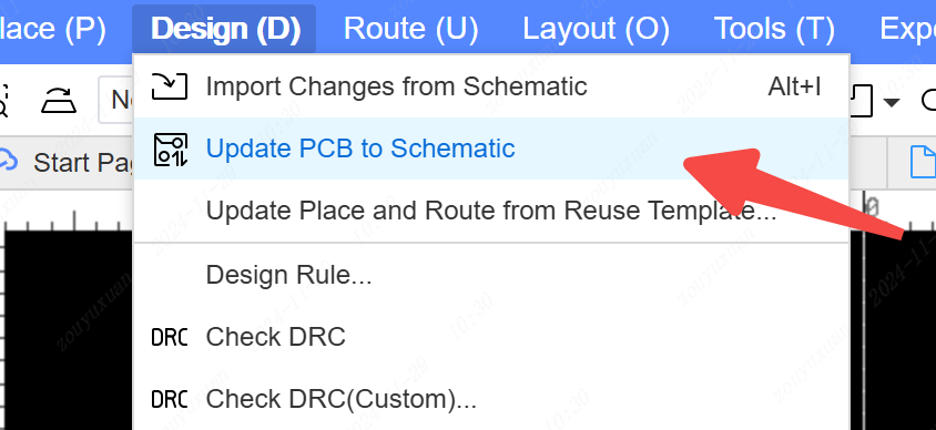
Supports updating from PCB to schematic.
Entry : Design - Update PCB to Schematic. Will update PCB component properties to schematic based on component unique IDs
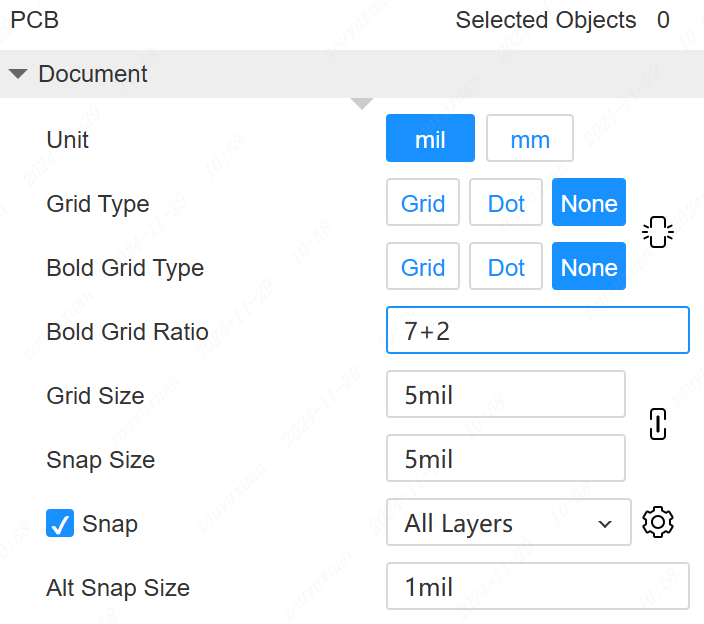
- The grid and raster settings in the Properties panel on the right side of the canvas support equal scale linkage

- Settings in the properties panel on the right side of the canvas are supported to be stored in the file
- Support for PCB reassignment of bit numbers.
Entry: Design - Assign Bit Numbers
Support for drawing in the blank area of the conductor
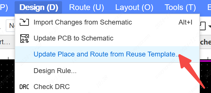
Support to create PCB by reusing block project.
Support to call PCB of multiplexed block project when schematic to PCB is converted.
Entry: New - Reuse Block, will automatically create PCB.
The PCB module that has been called supports updating the layout entry again from the PCB of the multiplexed block project. Design - Update Layout Wiring from Multiplexed Blocks
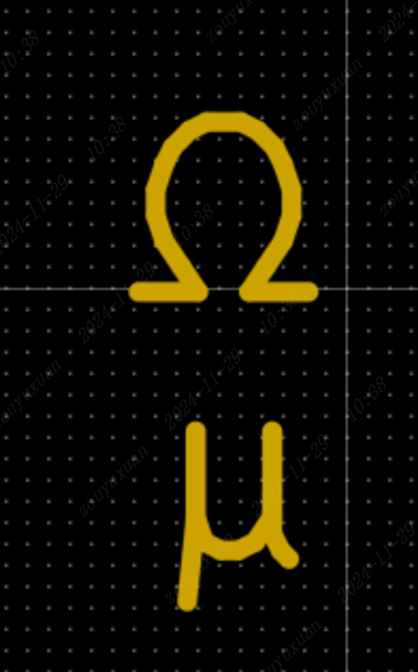
- PCB built-in default font support for Ω and µ characters
Components can be combined when only the properties of the component are selected.
Duplicate layout and wiring function supports duplicating the location of silkscreen text and other components.
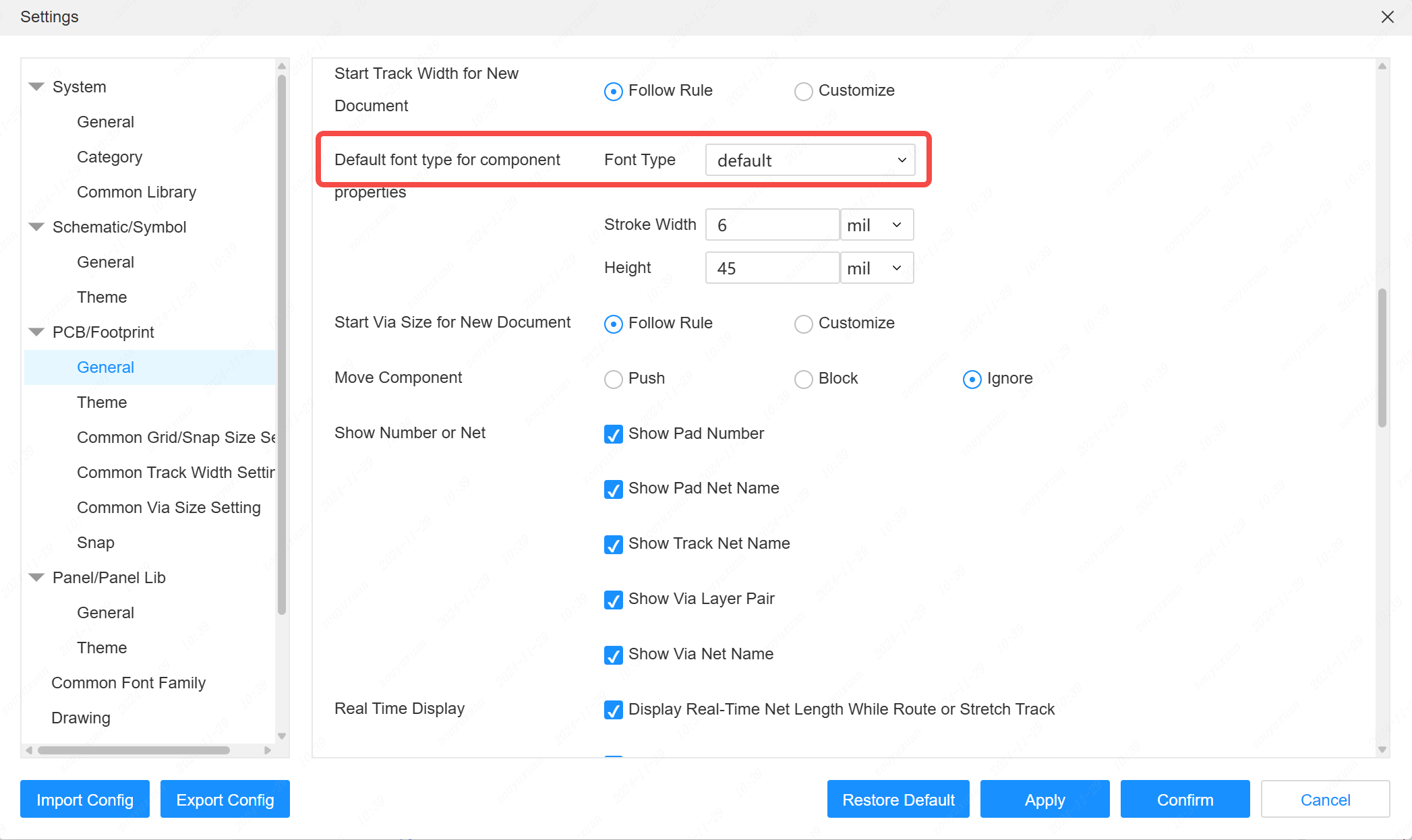
Supports default font and text size settings when placing packages.
Entry: Settings - PCB - General - Component Attribute Default Font.
If the text size of the attribute has been set when the package is edited then the size and font at the time of editing will take precedence.
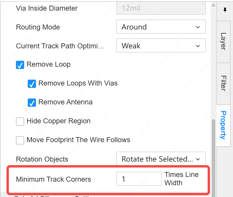
- Support for setting the minimum corner of the stretched wire.
Entry: Properties panel on the right side of the canvas - Minimum corner of stretched wire
- Placement of text placement and support for setting more styles after pressing the TAB key
When dragging the package, support the shortcut key of mirroring to mirror the package as a whole.
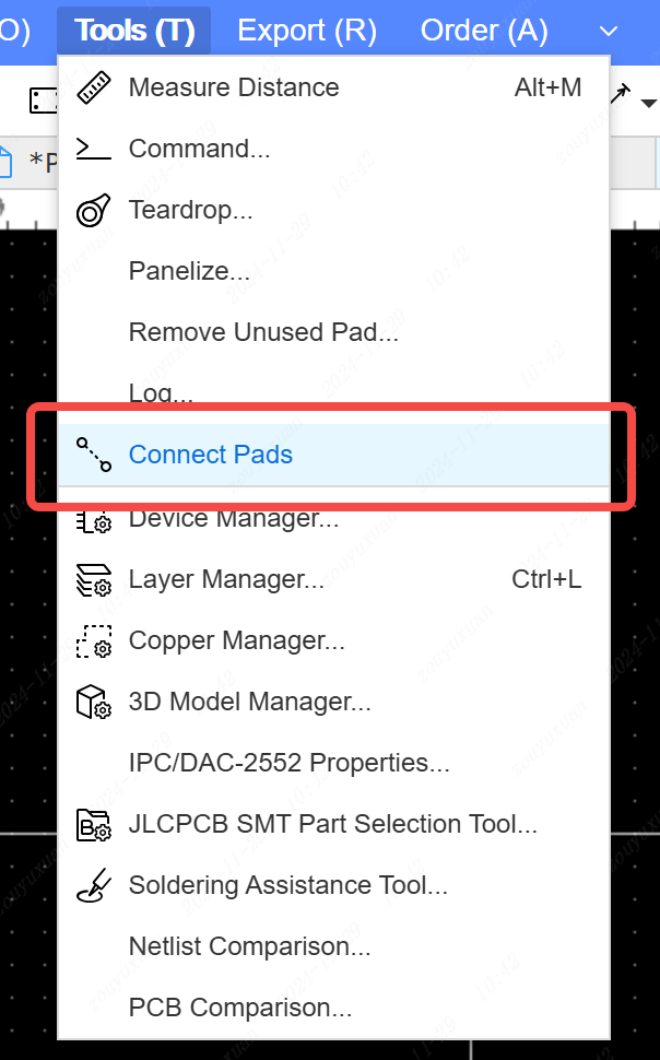
Support pad connection function to facilitate rapid network generation without schematic PCB.
Entry: Tools - Connect Pads
- Soldermask extension for Design Rule pads changed to 2mil by default
- The Remove Slit Hole in the Copper Layout Properties panel supports the removal of slit holes based on their size.
- Drill files with a circular trenching area diameter of less than 6.5mm are exported to Gerber's NPTH file.
- A new Drill_PTH_Through_Via.DRL file is added to the exported Gerber to differentiate between through-hole and via-hole drilling files.
- Automatic switching to the top layer for routing in non-signal layers.
Panels
- Optimize hover and select styles
- Canvas operations update right side properties in real time
- Importing SVG supports displaying size and type
- Optimize the interaction of displaying anchor points and control points of elements.
- Combine Pieces and Bezier curves into Pen tool.
- Optimize the interaction between fold lines and bezier curves to pen tool.
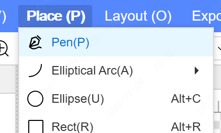
- Support panel dragging adsorption
- Supports four vertex drag rotation when the element is selected.
Other
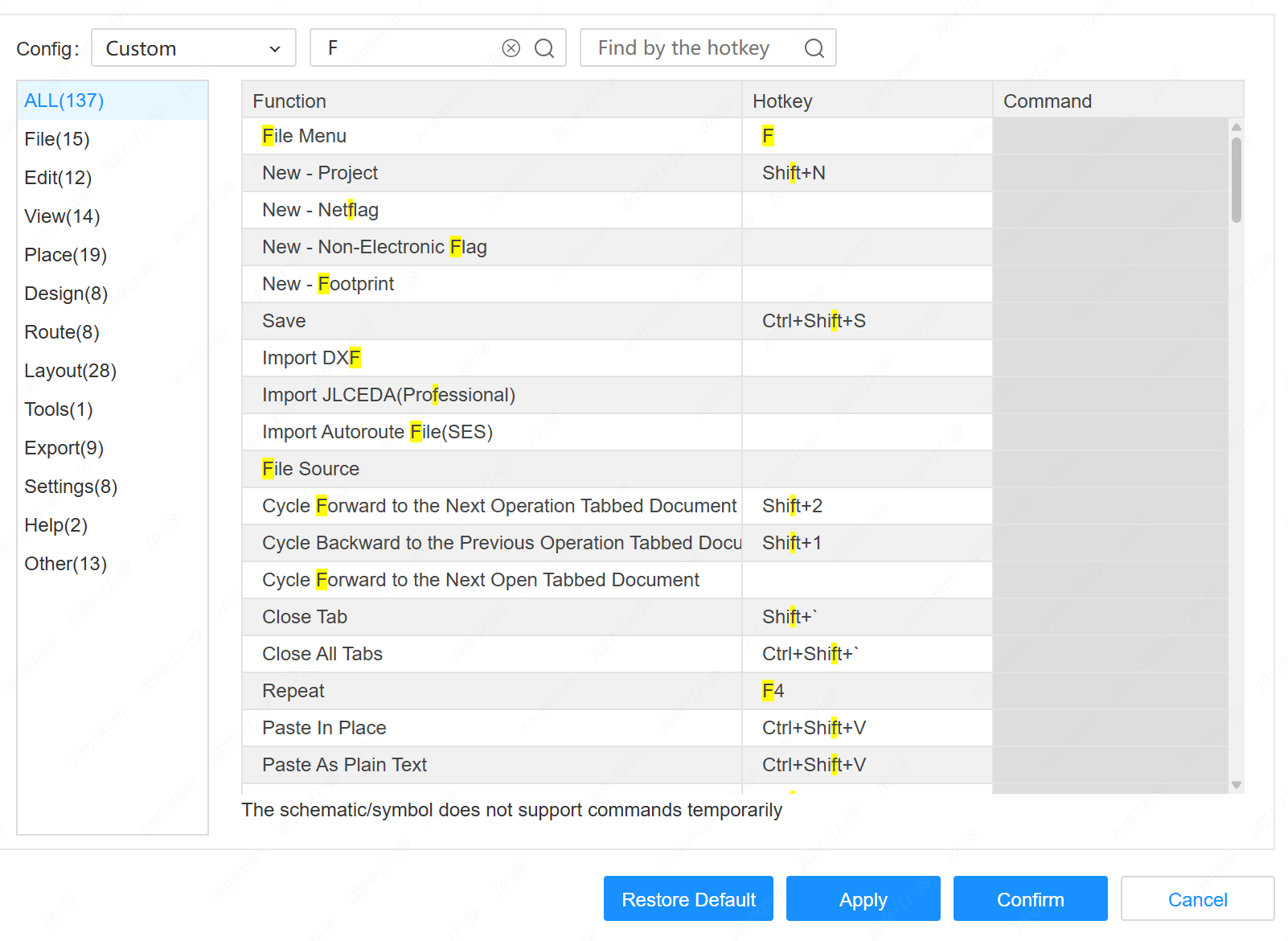
- The shortcut theme is split into Pro and Standard, and the Pro theme adjusts the shortcut keys for some functions.
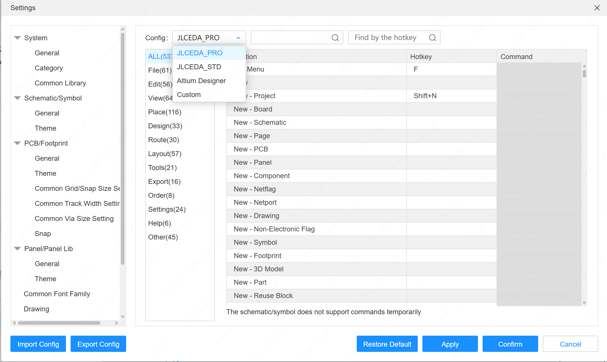
Most of the functions support setting shortcut keys
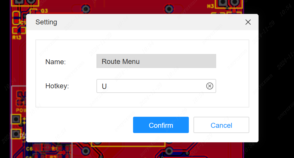
Support setting global shortcuts and menu secondary shortcuts for each menu by CTRL+left click.
How to use: Expand a menu by mouse, press CTRL+left button, popup window to set
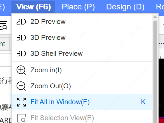
Adapt all as shown below, pressing shortcut K directly in the canvas is equivalent to pressing F6, then F.
Touchpad gesture support
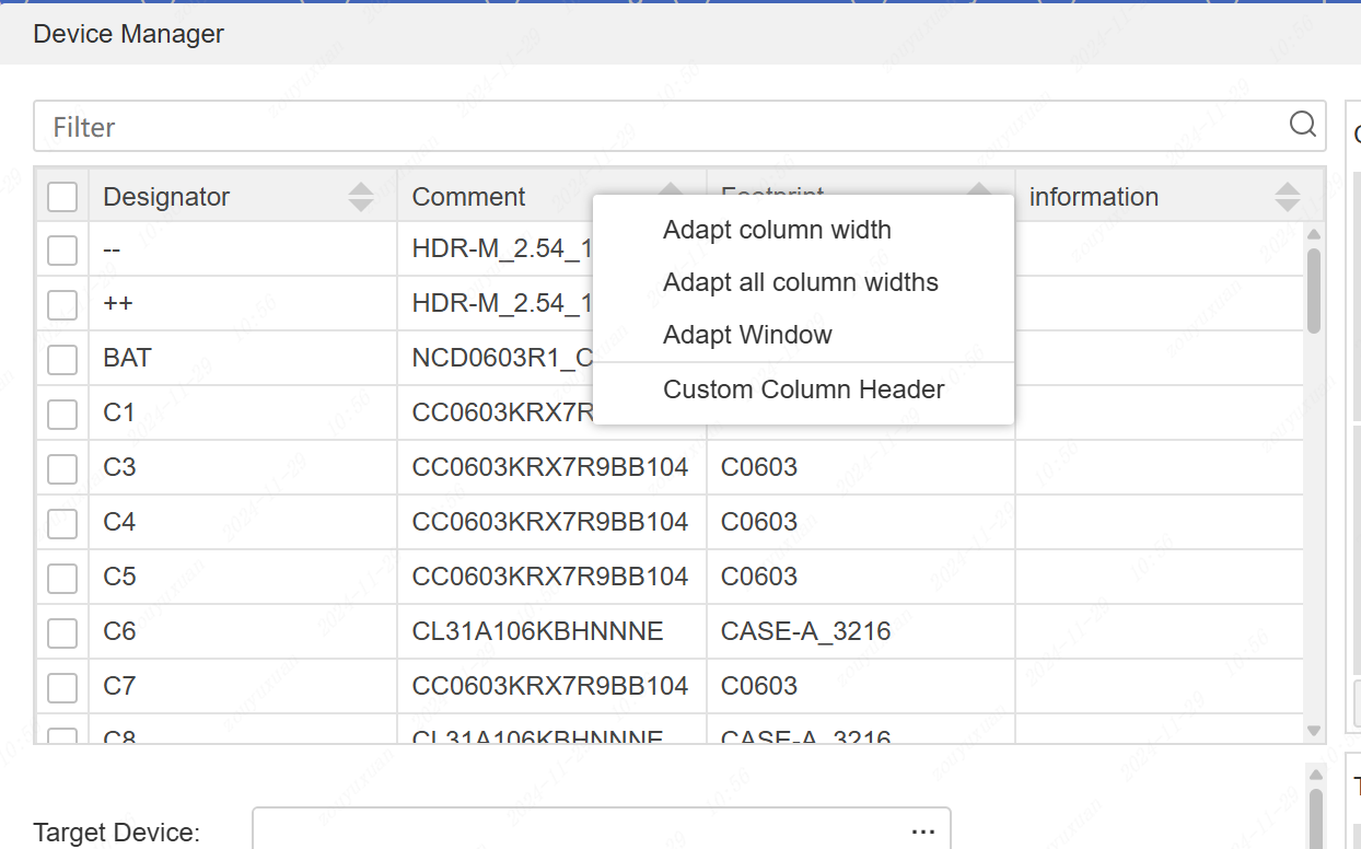
Package Manager/Device Manager/3D Model Manager support customized list header.
Entry: left list - table header context menu
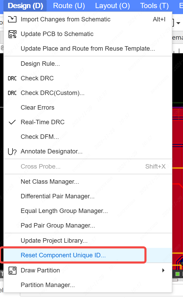
Schematic and PCB support for resetting component unique IDs.
Entry: Design - Reset Component Unique IDs
- Stretch width of left/right/bottom panels supports larger values
- Filter box of package manager/3D model manager changed to continuous display
- Left side page tree supports F2 to rename document and Enter to open document
- All numeric input boxes support simple quadratic operations.
- Support find function by shortcut key in Set Shortcut Key dialog box
Migrate standard version files to support paging
Add the option of whether to enable the function of dragging an element by CTRL for copying in the settings dialog, PCB does not enable it by default.
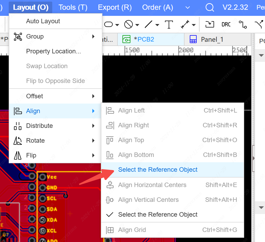
The alignment feature supports whether or not to enable the Select Reference Object feature.
Entry : Alignment - Select Reference Object. When turned on, alignment will select the object before aligning it
Adjust all document titles to 1~128 characters in length.
Remove 2 character minimum keyword limit for library search.
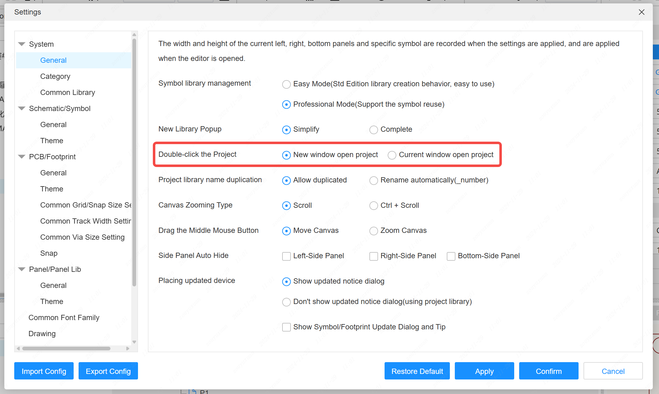
Settings add double-click to open the project in the current editor window to open or a new window to open.
Entry: Settings - General - Double-click Project
- Add a feedback menu to the help menu
- Optimize the display of large popup window, it can be displayed completely in small screen without blocking the buttons
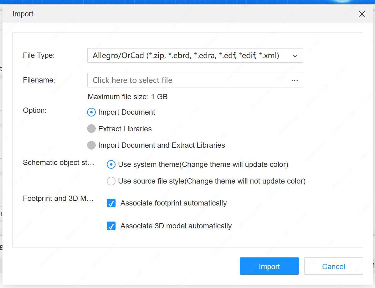
- Support importing OrCad schematic, edf format.
Client
- The client supports more CPU architectures. Longxin loong64, Shenwei sw64, Kunpeng/Fetion/Applearm64
- Split client upgrade detection for different CPU architectures
- Optimize the search index generation speed of the local component library, support more parameters for searching