V1.8.x Update Notes
Schematic
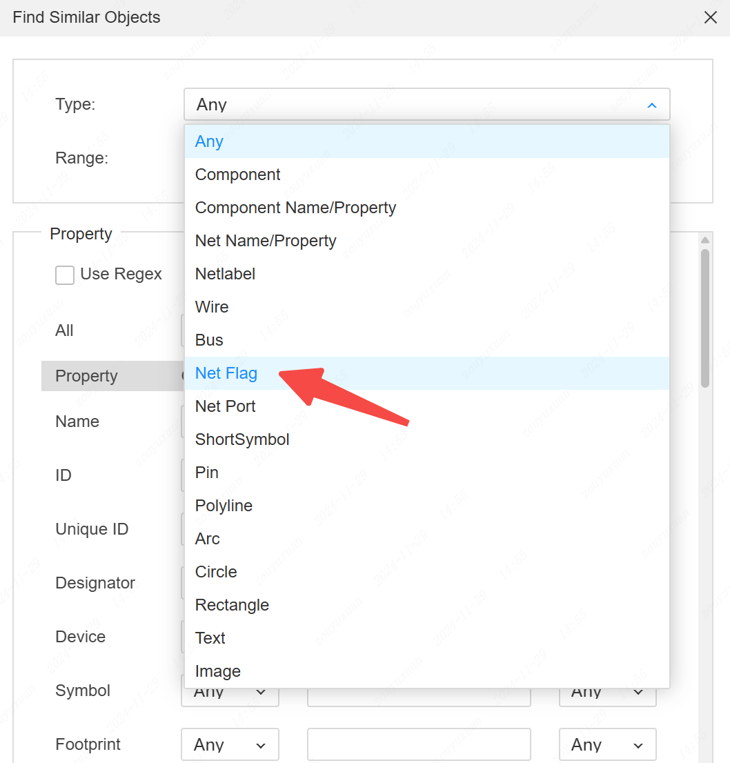
- Support for searching network tags
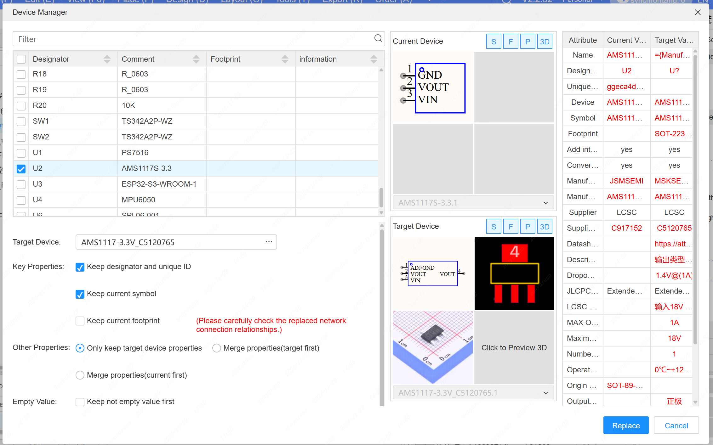
- Support for the device manager, enabling device parameter substitution (does not support simultaneous substitution of symbols and packages).
Entry: Top menu - Tools - Device Manager
- When drawing wire buses, support for switching the wiring direction using the spacebar.
- Add a "Request Drawing Library" button to the component placement dialog box and the bottom component library.

When searching for all objects, support for selecting and highlighting all objects.
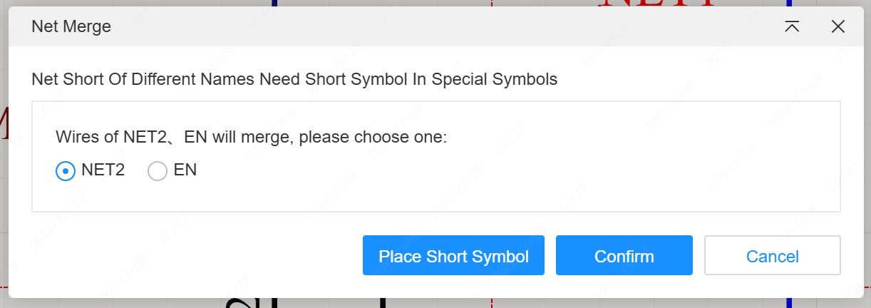
Remove the network segmentation pop-up window when splitting wires.
The input box for attribute values now supports Greek characters.

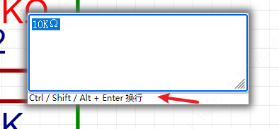
- A regular text input box supports ALT/SHIFT+ENTER for line breaks (properties such as network names and bit numbers do not support this).
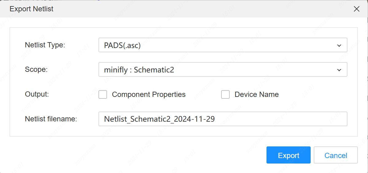
- Support for exporting the netlist of PADS9.5
- When the network port and wire name are not consistent during placement, support for a pop-up prompt to modify the wire name.
- The left tree supports opening multiple selected pages simultaneously.
- A new "Design Rules" tab has been added to the bottom panel.

- The exported BOM supports exporting the "Add to BOM" and "Go to PCB" attributes. Configuration settings are on the left side.

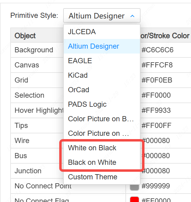
- The schematic theme now includes a white background with black graphics and a black background with white graphics.
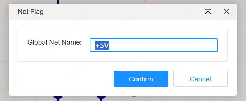
- When placing network identifiers, support for setting the global network name using the TAB key.
- Removing network ports supports automatic clearing of wire names.
- Components not included in the BOM and not transferred to the PCB are not subject to design rule checks.
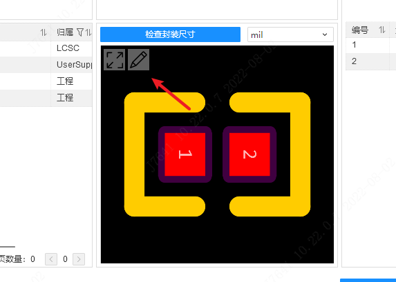
- The package preview window of the package manager and the right-click menu in the package list have added an "Edit Package" function.
- Deleting the reused symbol in the engineering library supports prompts for whether to delete the corresponding schematic simultaneously.
- CTRL + ALT moving the wire name supports wire not following.
- Reconfigure the wire routing logic to optimize the routing operation.
Panel
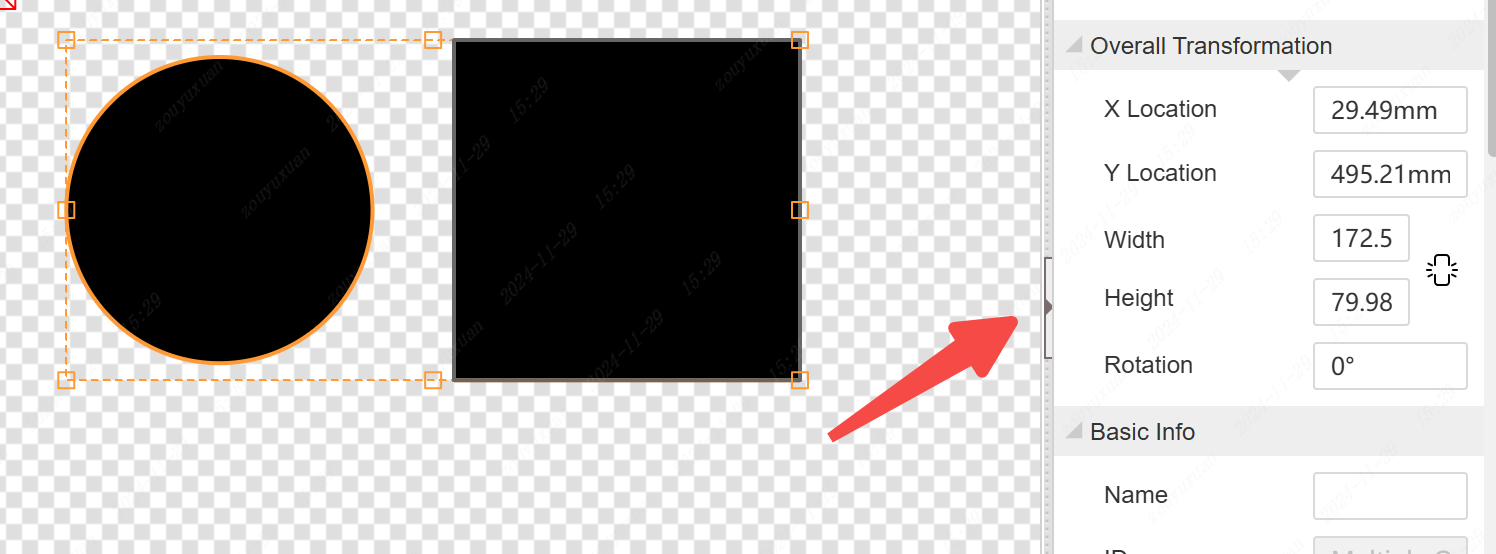
- Support for arbitrary angle dragging and rotation of graphic elements.
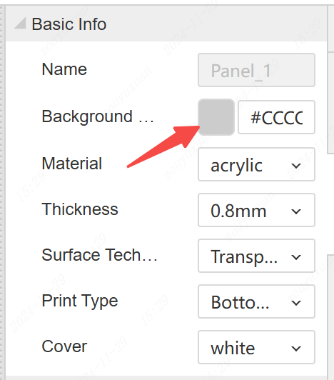
- The 3D preview panel supports setting the background color.
- When multiple objects are selected, the property panel supports overall position movement.
PCB
- Support for reusing combined layout and routing. Usage method: Draw multiple circuit groups on the schematic, update to the PCB, select a group for layout and routing, select the laid-out objects, right-click to create a combination. Other modules also right-click to create combinations respectively. Select the first unfinished layout and routing combination, and click: Layout - Reuse Layout and Routing. The cursor selects the previously completed layout and routing combination, and the layout and routing will be automatically completed.
- Support for setting pad pairs, facilitating equal-length routing. Entry: Top menu - Design - Pad Pair Manager
- After modifying the case height of the PCB, support for synchronizing with the 3D case preview.
- Support for saving PCBs with a large amount of copper pouring and a large amount of custom font text.
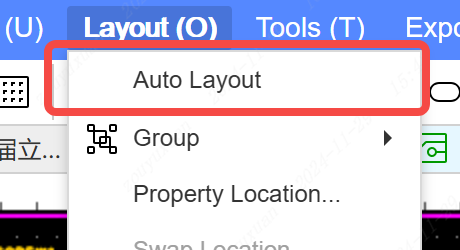
- Support for the preview version of automatic layout (under continuous development). Entry: Top menu - Layout - Automatic Layout
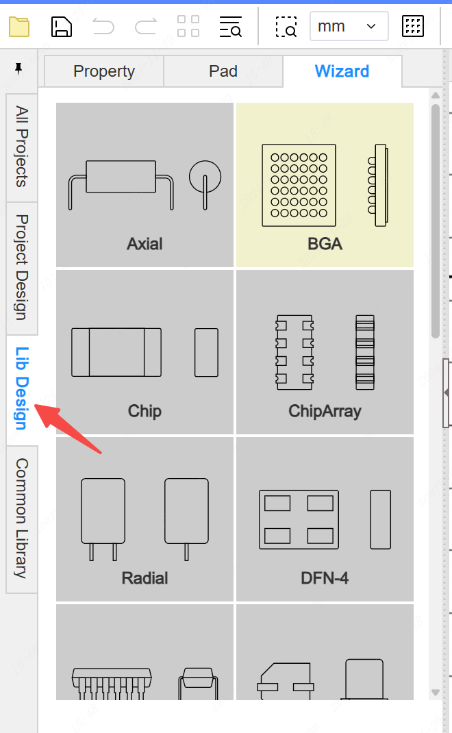
- The left tab in the packaging editing interface supports the packaging wizard.
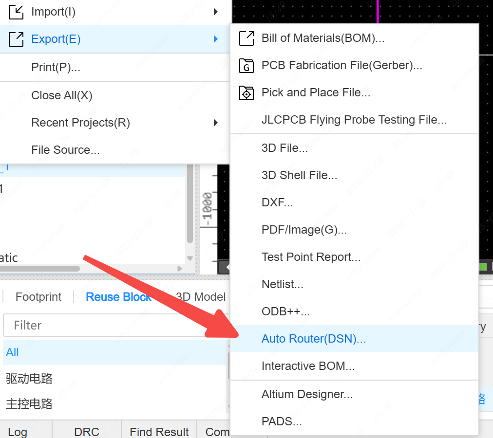
- Support for exporting and importing automatic routing files
PCB one-click ordering supports detecting flying wires, detecting whether there is a frame, and detecting DRC.
Routing supports recording the last set wire width.
3D case ordering supports detecting whether there are 3D case primitives.
Adjust the highlight effect of component selection and remove the highlighted box effect.
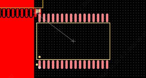
Via holes support adding within the copper pour of the corresponding network.
Optimize the exit and entry routing of solder pads.
Right-click editing of the component's package is only applicable to the current component.

- The relative offset function supports recording the previous parameters.
- When dragging and moving components by selecting a frame, support for continuous connection of wires without breaking.
- Equal-length adjustment supports automatically finding the starting position for equal length.
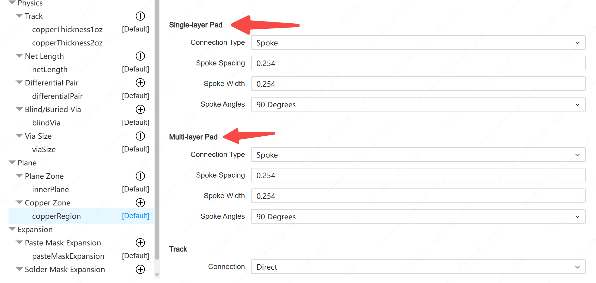
- The copper pour and inner layer design rules support the respective connection methods of solder pads and plug-in solder pads.
- The drop-down option supports arrow key selection.
- All network-enabled objects support manually creating a network in the properties panel
- Support shortcut key ctrl+SHIFT+V Paste board to keep the bit number unchanged and hide the flying line layer, convenient manual Mosaic
- Drop text support TAB key to modify text attributes
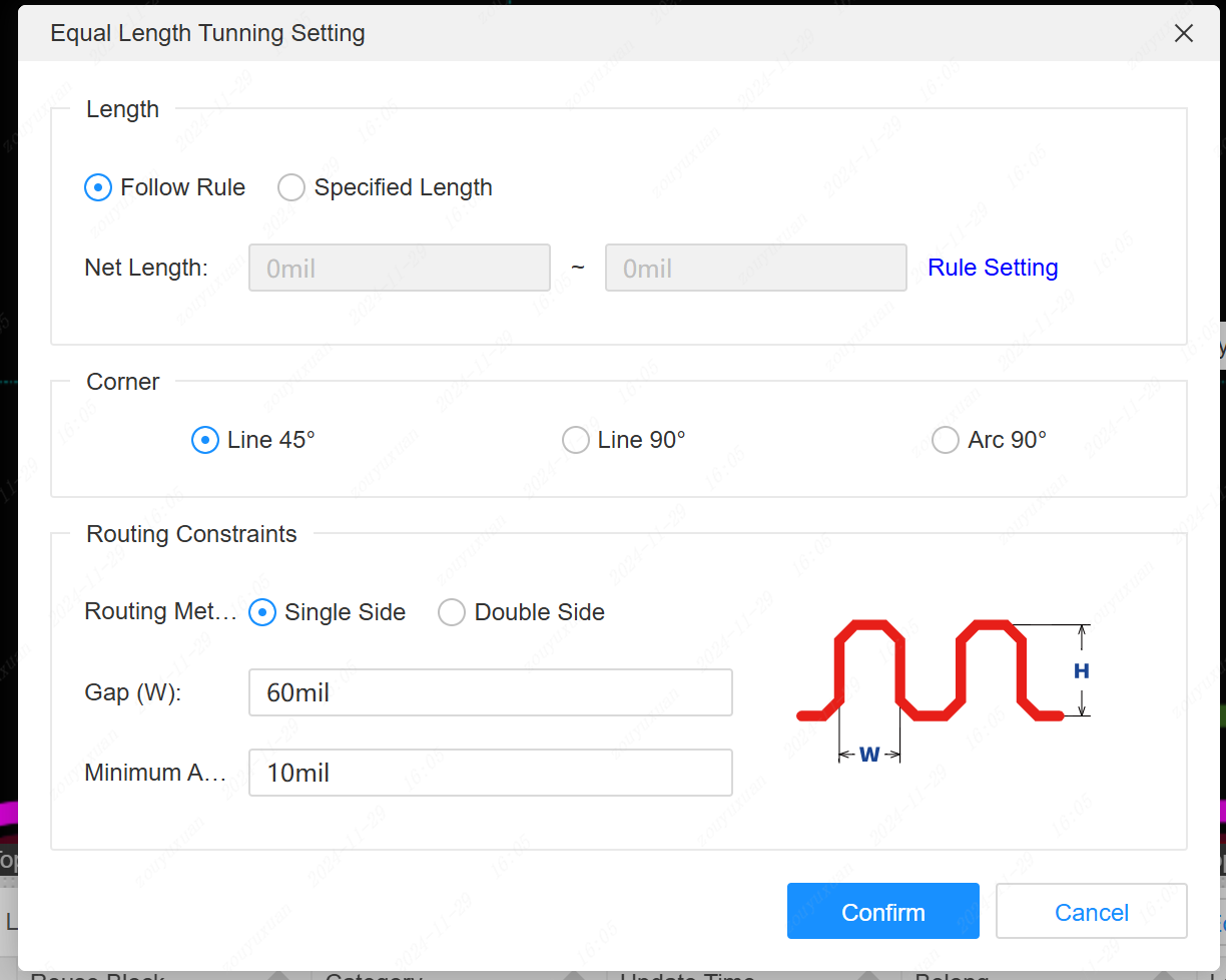
- The Equal-length adjustment dialog supports setting the required additional length. Press TAB when adjusting the length.
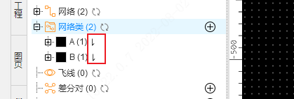
-Left network Tab supports wire length sorting for network classes, differential pairs, pad peers, etc
- Support for drawing self-intersecting multi-morphing primitives, automatically split multiple disjoint primitives after drawing
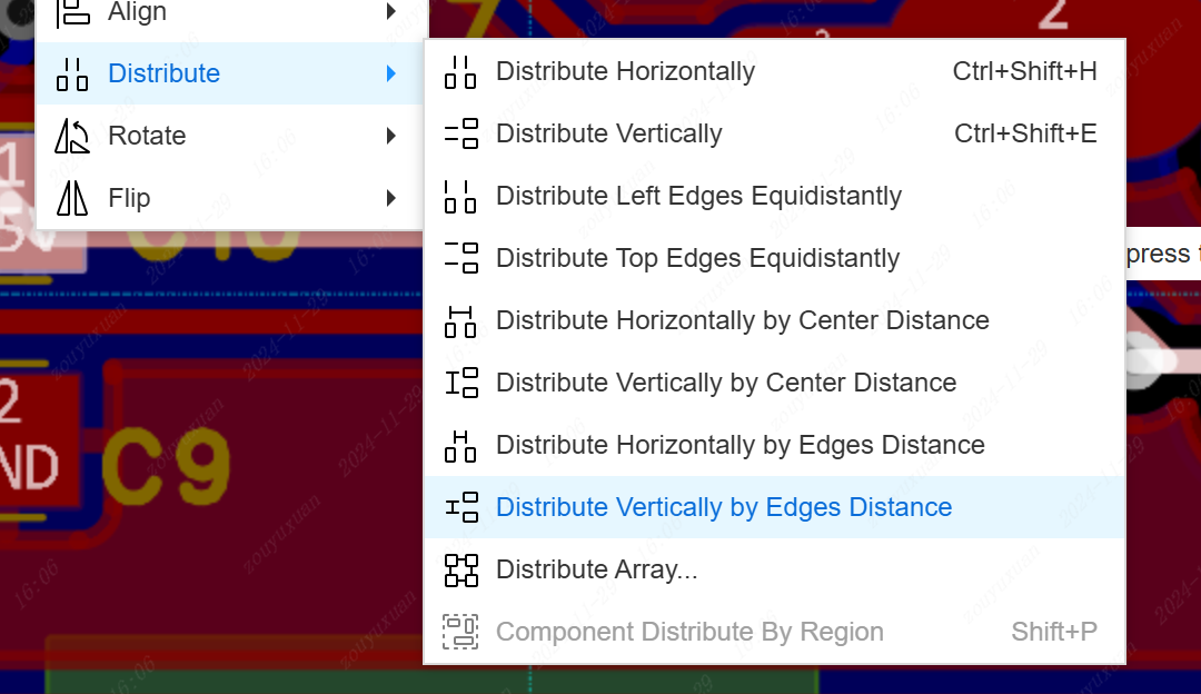
- Specify that the spacing distribution supports both center spacing and edge spacing
- Equal-length network groups support the distinction of networks already belonging to other network groups

- 3D preview adds import change button to support importing PCB changes

- Optimize the fan-out of pad outgoing and incoming wires
- Differential pair routing supports pressing the space bar to switch wiring corners when starting wiring and punching holes
- Support continued stretching after stretching the wire fusion node
- Arc mode routing is supported to finish in arc mode at the end
- The component layer cut shortcut is left blank by default
- Support different network names for pads with the same pad number in the package
Others
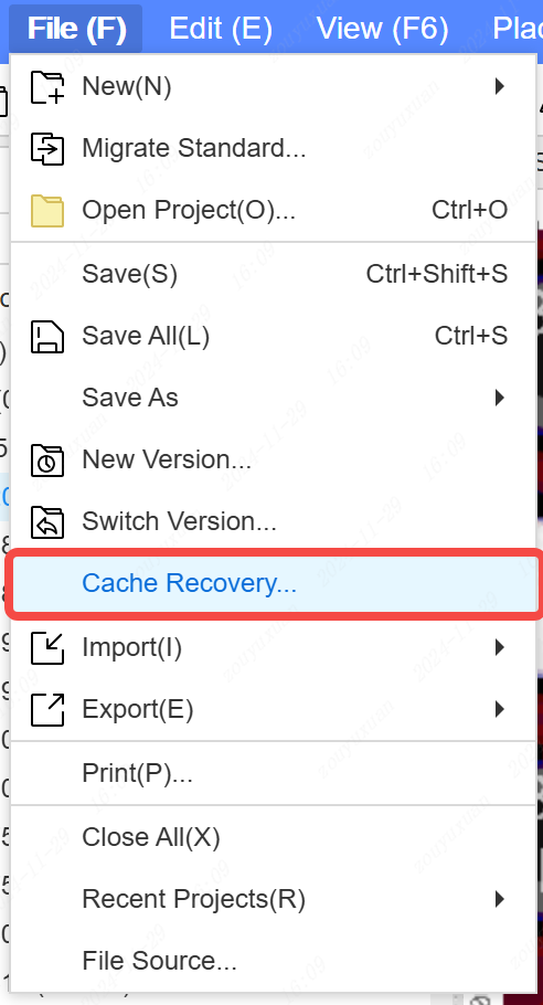
- Support project cache recovery. Five minutes automatically cached once in the local, accidentally deleted projects can be found here.
Entry point : Top menu - File - Cache Recovery
- Added project Tab to left panel
- Add a refresh menu to the document right-click menu of the Tab on the left diagram page
- Add a hint to sync data to the cloud in the top right corner

- Add an update button in the top right corner when a new version of the editor is released
- Custom keyboard shortcuts are supported for both the top menu and right-click menu functions.
Entry : Top menu - Settings - Shortcut
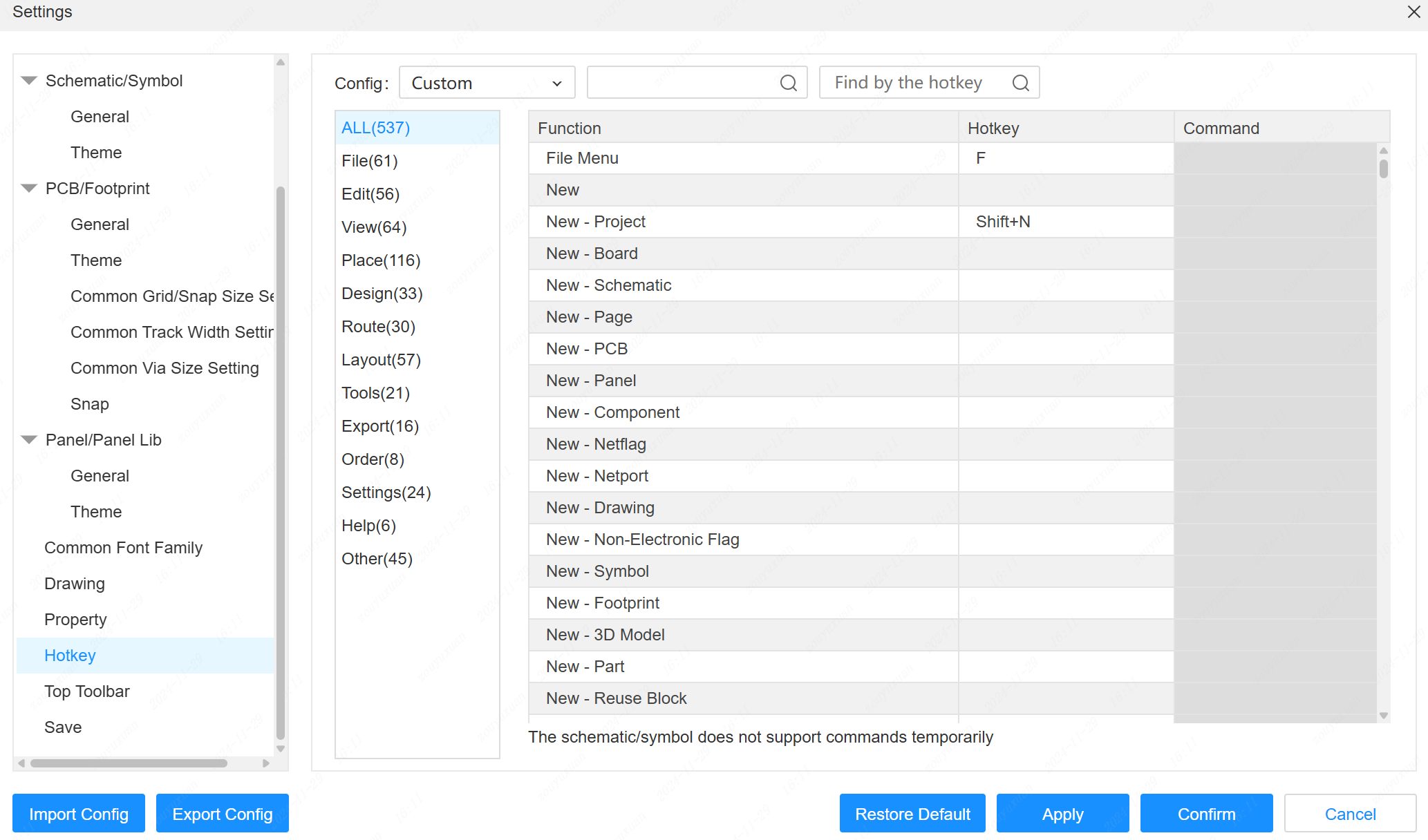
- Support single keyboard shortcuts to call out the top menu and display single key letters in the top menu.
Entry : Top menu - Settings - Shortcut - Theme switch to Altium Designer
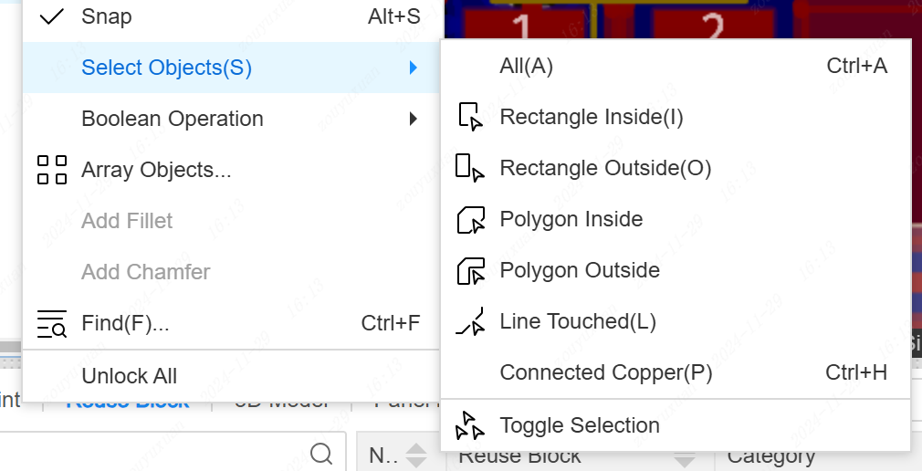
- Add rectangle interior selection to the selection menu
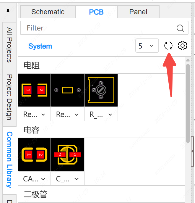
- Added refresh button to support reloading of common libraries
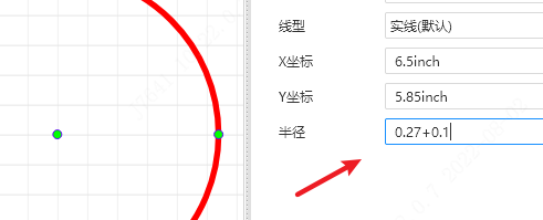
- Schematic, symbol, and numeric input fields in the panel support four operations
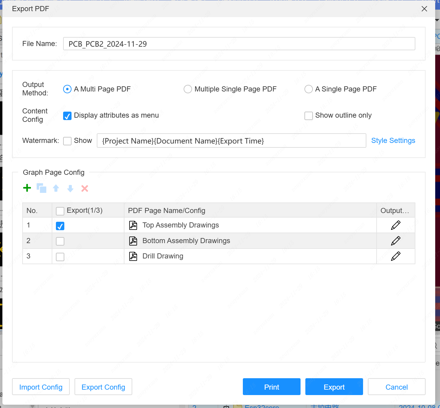
- Schematic and PCB support print menu.
Entry : Top menu - File - Print
- Copy and paste between schematic and symbol, PCB and package
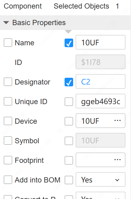
- Component property names support calling custom property values for display
- Migrating to Standard Edition does not require logging into Standard Edition again
- Cross-check supports multiple Windows
- Add project basic information and member information to the right property panel of the project blank page
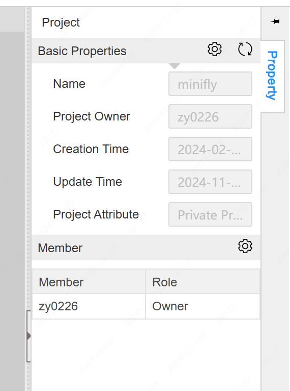
- Add the permission role of the corresponding project to the left project list
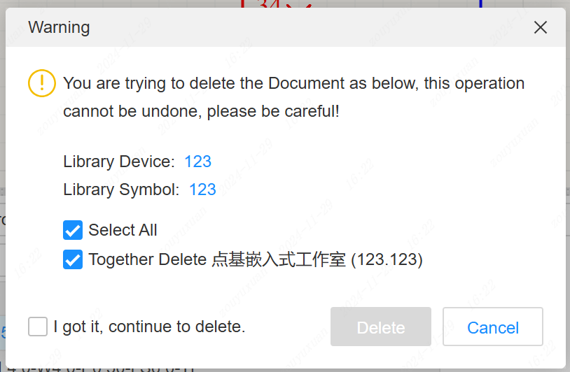
- Solve the problem that engineering library classification is not documented
- Whether symbols and encapsulation are removed when removing devices from the engineering library
- Save supports a Save as popup when opening a document without editing permission
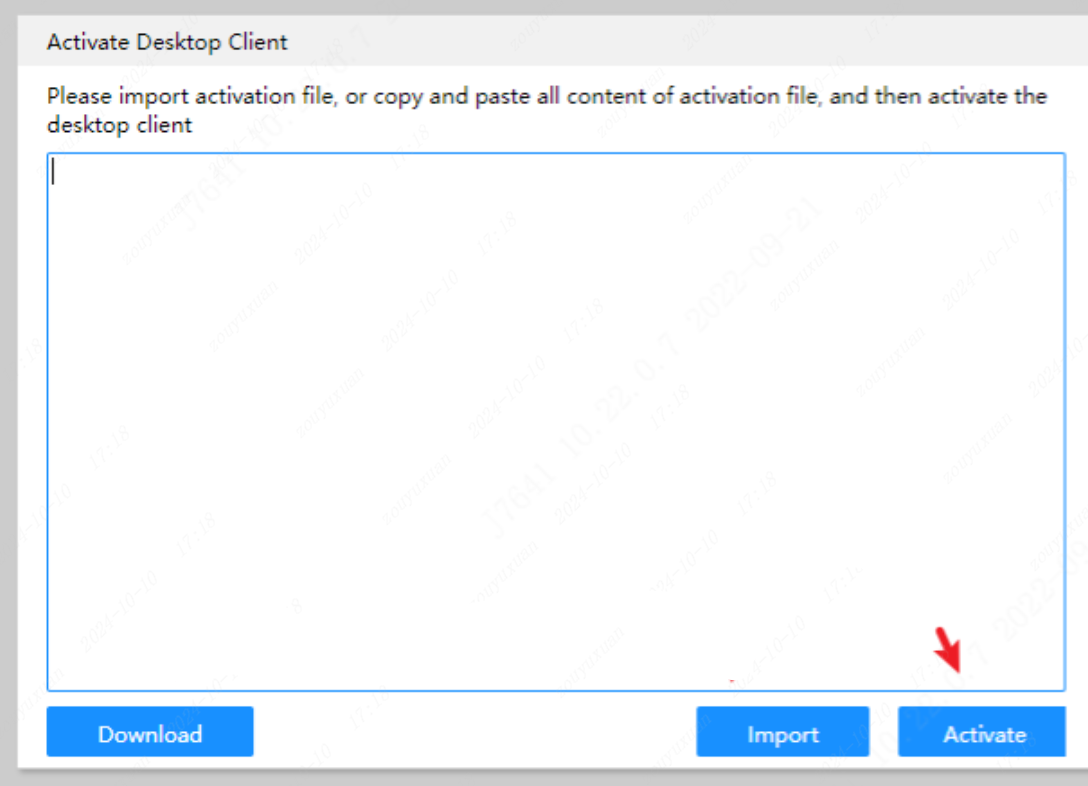
- Client activation popup is adjusted to support pasting activation codes directly. Client upgrade is expected in two weeks
- Client supports loading different project directory paths up to 10.
Entry Point : Settings - Client Settings - Project directory